| The Dornier DO-80 |
|

|
The Dornier DO-80 Analog Computer |
| The Dornier DO-80 |
|
|
|
|
|
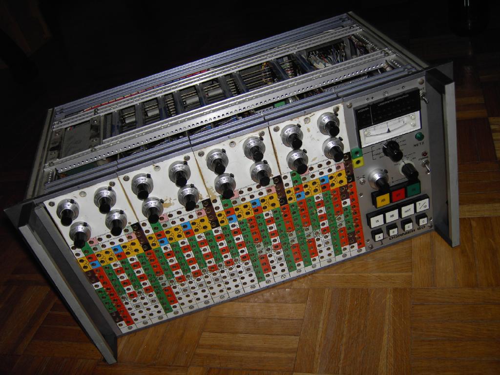
The Dornier-80 is the smallest model of the analog computers built by the German manufacturer Dornier. This system was mainly used for dedicated control applications (for example in nuclear research reactors) and for educational purposes. The system is based on standard components so there are no chopper stabilized, drift compensated operational amplifiers, no digital interfaces like digital potentiometers, etc. It is a very simple and basic system but a charming one. It is simple to maintain and repair (even without schematics, which I unfortunately do not have - if you happen to have the drawings for the system, etc. please let me know!) and easy enough to operate to invite for playing around with differential equations. |
|
|
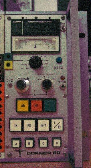
One of my two DO 80 computers was donated by the Institut für spanende Fertigungstechnik of the Universität Dortmund. I would like to thank Prof. Weinert and Mr. Krückendorf from the institute for this donation. Many of the following pictures show this system since it is in better shape then the other one. The picture on the left shows the older version of the control panel of the system. It is divided into the following three parts (from top to bottom):
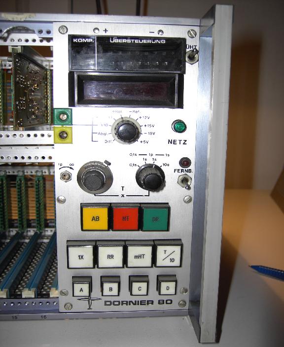
The picture on the right shows the more modern variant of the operator control panel which is more or less identical to the older version apart from the fact that a digital four digit voltmeter is used instead of the former compensation voltmeter. Note: When you ever encounter weird readings on this digital instrument be sure to check the +5 V supply for ripple and for correct setting. The voltmeter is quite sensitive to this! |
|
|
|
|
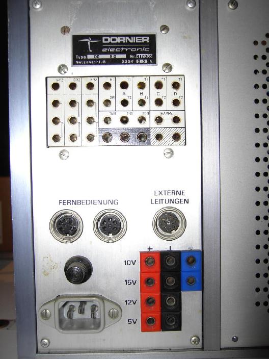
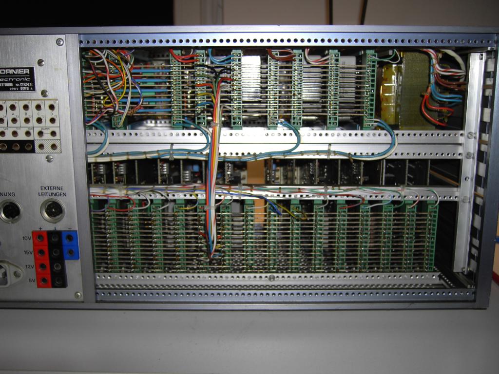
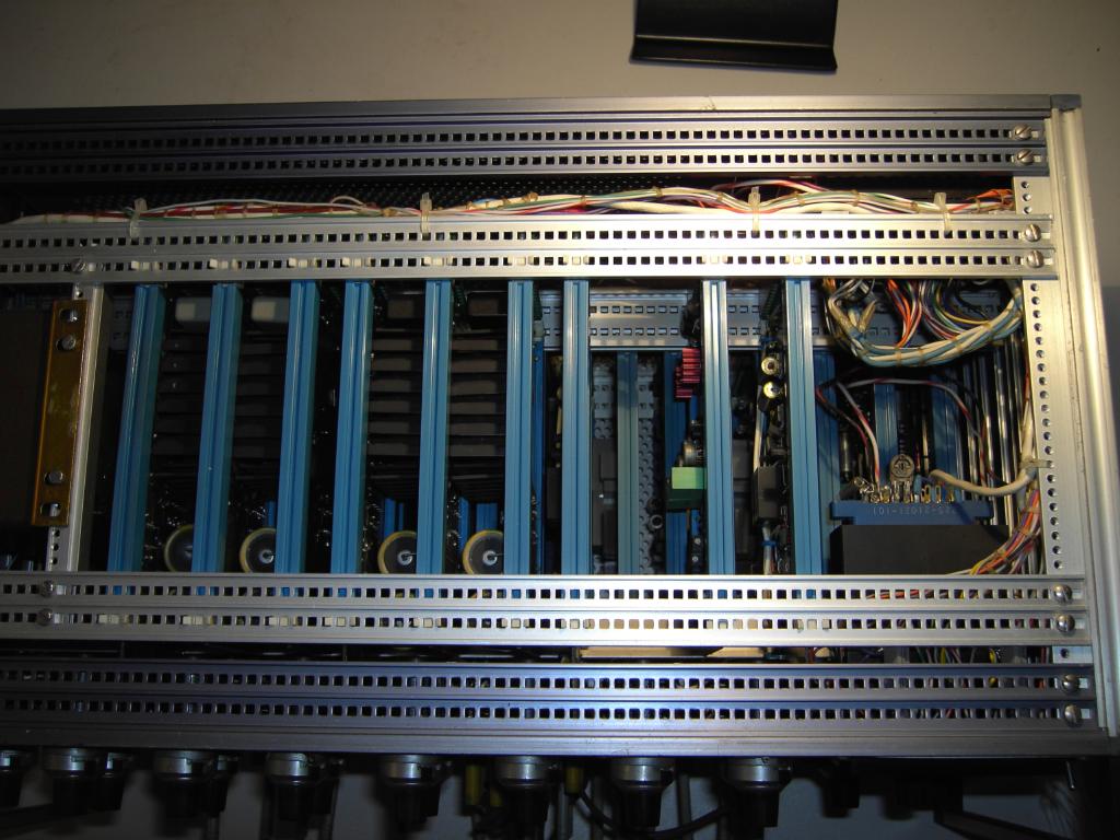
The following two pictures show the back of the DO 80 analog computer. On the left the interconnect panel is shown - this is where the trunk lines used to connect to oscilloscopes and x/y(t)-plotters end. Furthermore the control signals (halt, initial condition, run, etc.) are brought to this panel, etc. The picture on the right shows the overall back view of the machine. The bus system like interconnection scheme of the modules is clearly visible. |
|
|
|
|
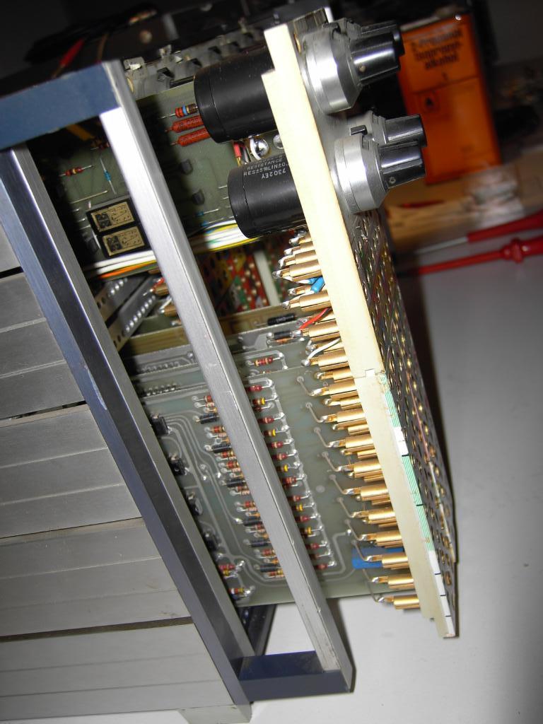
Removing the modules from the DO 80 is somewhat tricky. First of all you have to remove the backpanel to gain access to the rear of the modules. Then - after removing all front screws from the modules - apply some force to the back of the modules you want to remove. Be sure to press against the potentiometer module on top as well as on the associated bottom modules. One potentiometer module holds four analog/digital modules. |
|
|
|
|
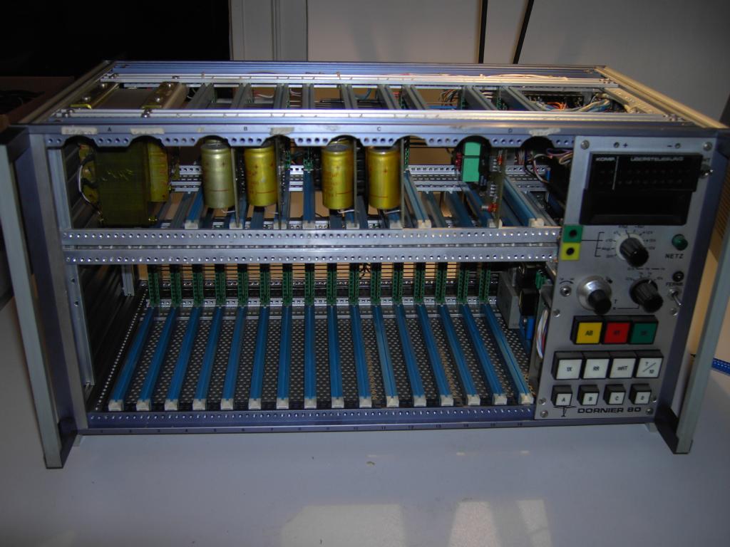
The two following pictures show the nearly empty system drawer. The remaining cards comprise the power supply system and contain the various voltage regulators. |
|
|
|
|
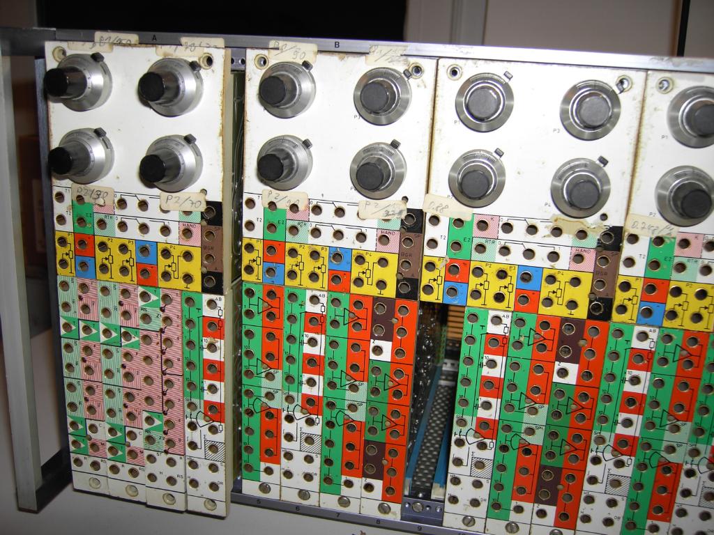
The following pictures give an impression of the various analog and digital modules which can be used in the DO 80 computer. |
|
|
Top view of summer module. 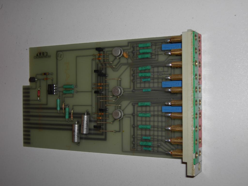
|
Front view of summer module. 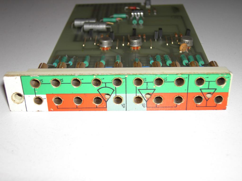
|
|
Top view of integrator module. 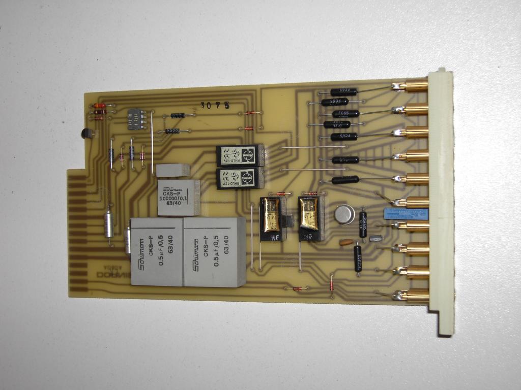
|
Front view of integrator module. 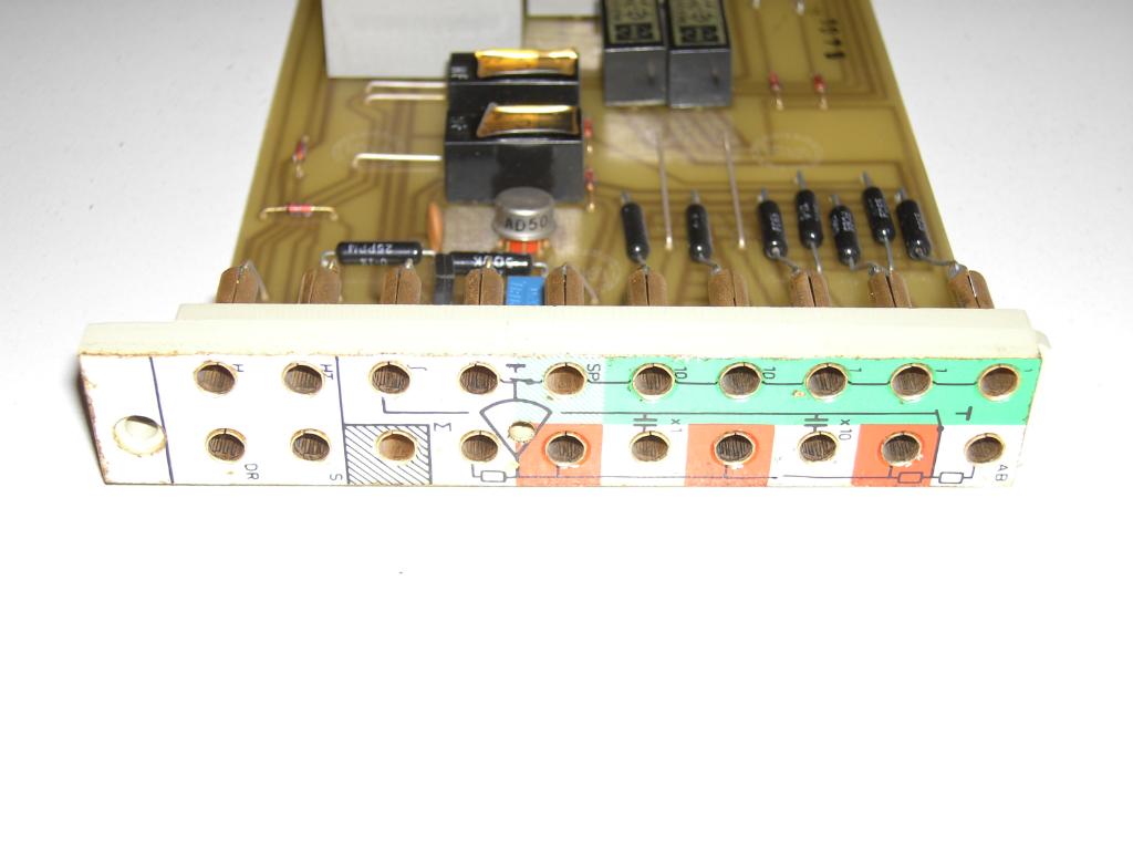
|
|
Top view of multiplier module. 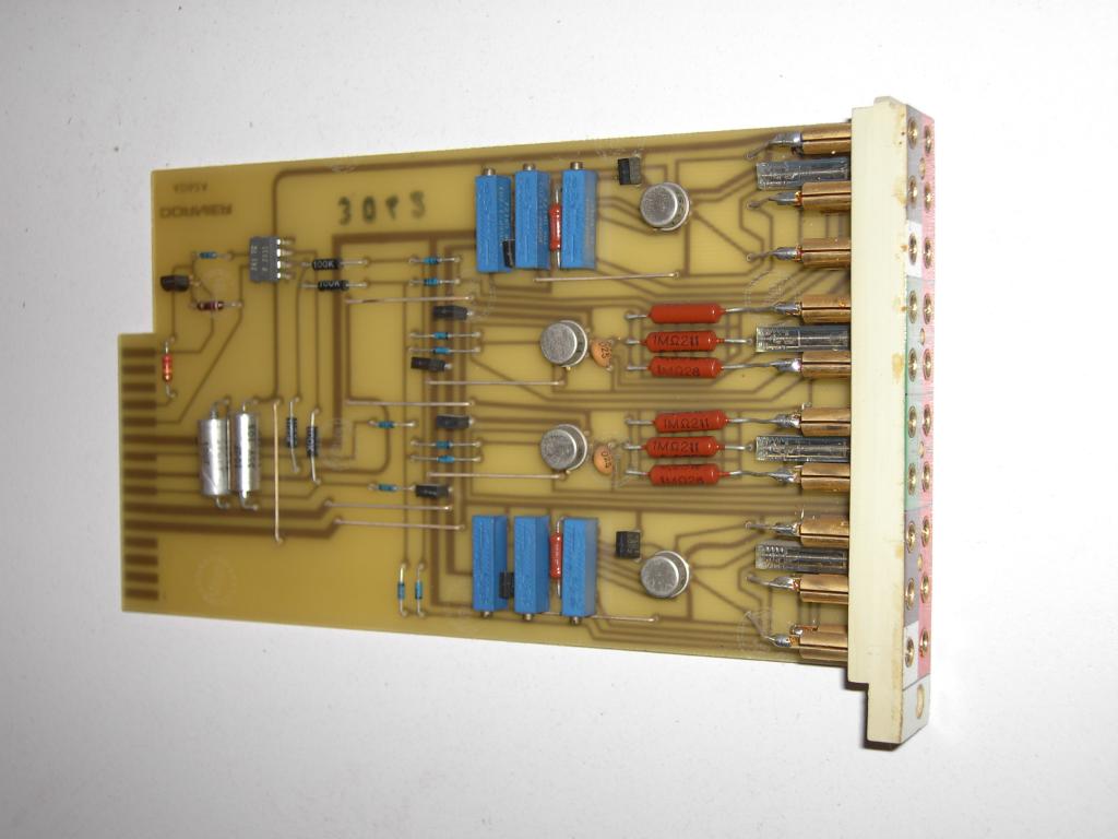
|
Front view of multiplier module. 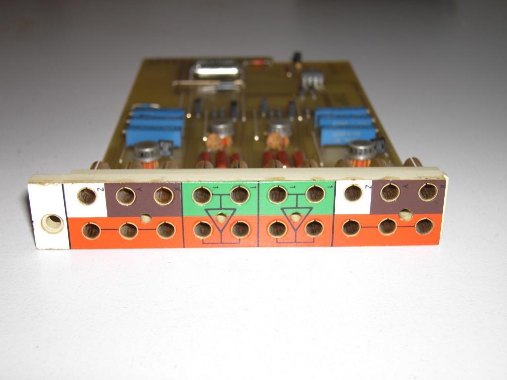
|
|
Top view of function generator module. 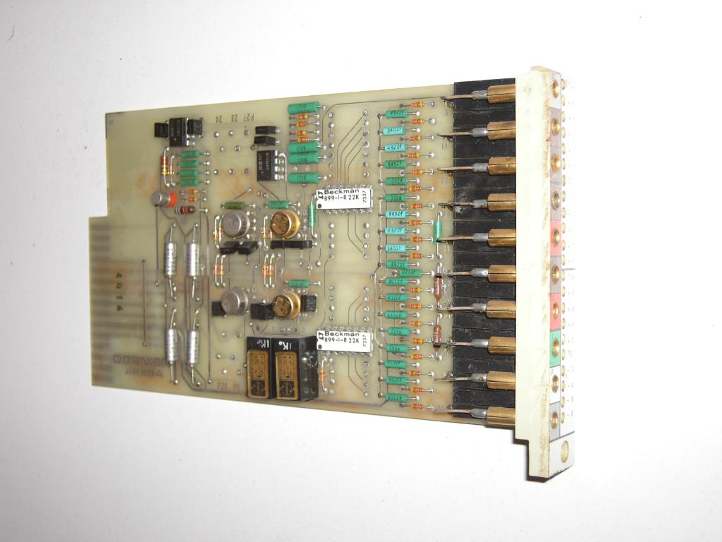
|
Front view of function generator module. 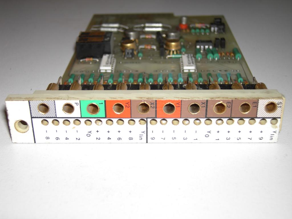
|
|
Top view of potentiometer module. 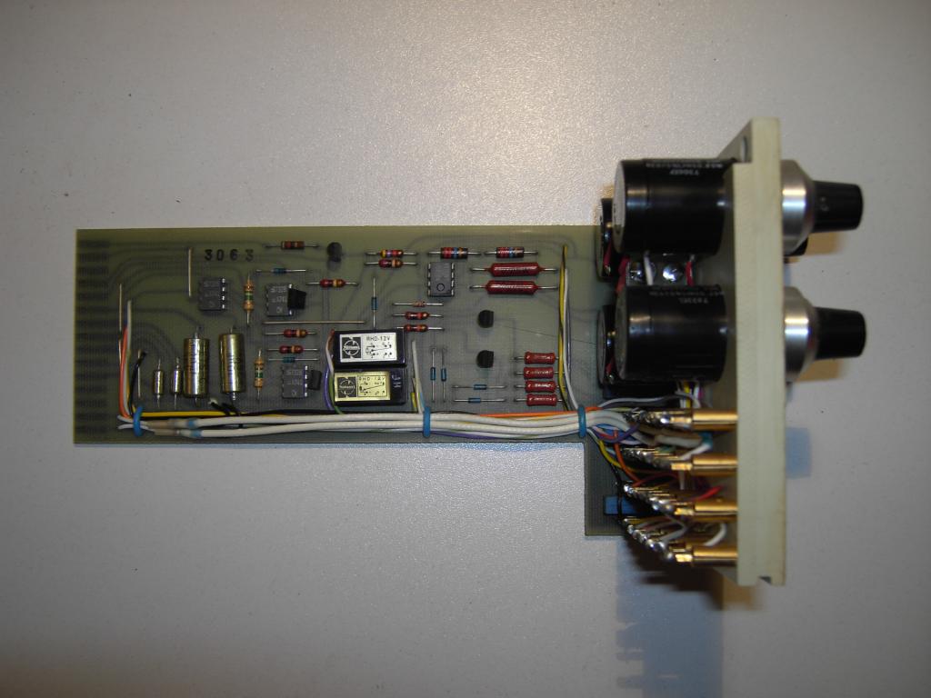
|
Front view of potentiometer module. 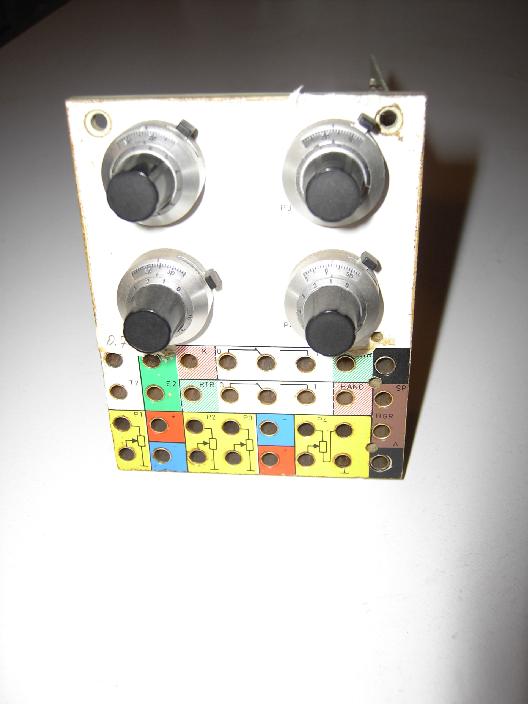
|
|
Top view of flip flop module. 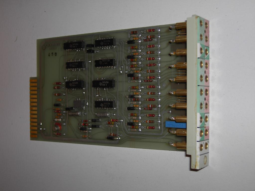
|
Front view of flip flop module. 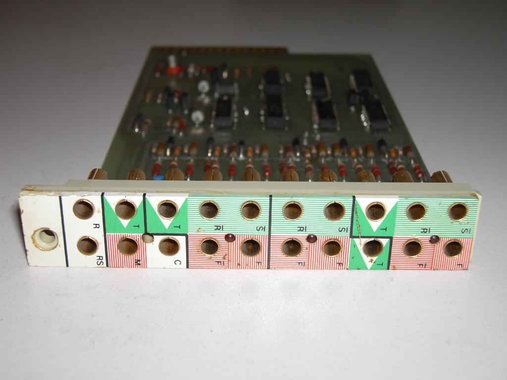
|
|
Top view of countermodule. 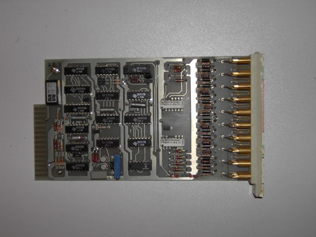
|
Front view of countermodule. 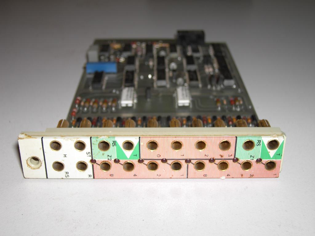
|
|
Documentation:
|
|
| 11-JUL-2006 |