| The Dornier DO-960 |
|
The Dornier DO-960 Analog Computer |
| The Dornier DO-960 |
|
|
|
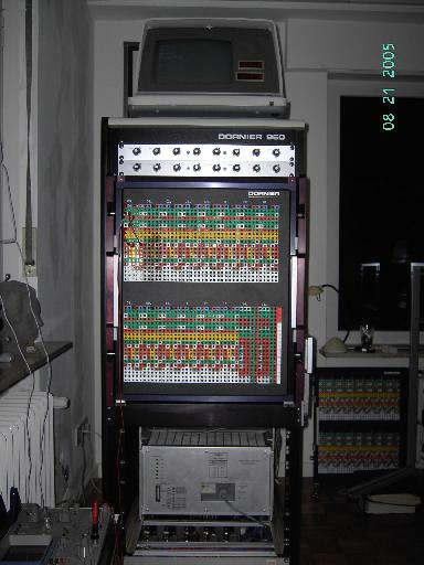
The name "Dornier" is normally linked with advanced aircraft design - with airplanes like the DO-31 VTOL, etc. Not many people know that the very same company built wonderful analog computers which outperform most systems of other manufacturers by far. The system shown in the following, the DO-960 was Dornier's top system. Dornier started the business of building analog computers when they got into VTOL design (namely the already mentioned DO-31) - the mathematical problems posed by these aircraft made the development of advanced computer systems necessary. Since no digital processor then (and maybe even today) was able to solve all of the differential equations necessary to describe the airplane in detail, Dornier started building analog computers. The DO-960 was the last system manufactured by Dornier (as far as I know). It is a hybrid system, i.e. it consists of a complex analog computer as well as of a digital computer system which is interfaced with the analog part by lots of AD- and DA-converters, etc. The digital system controls the timing and read out bus selection of the analog computer as well. When I got the system it consisted of two racks mounted next to each other. Unfortunately, only the rack on the right contained analog computing modules while the digital parts were spread all over both racks. Worse, the digital control system was designed to be controlled by a Data General NOVA computer system which was replaced by a PC based solution many years ago. Since I did not want to bother with a flaky PC with a 20 MB hard drive and with lots of undocumented software I sought a way to get around this PC solution. After reading lots of the documentation that came with the system it became clear to me that Dornier had two main versions of the DO-960 on the market: An entry level system with a digital processor with ROM based BASIC interpreter and a high end system with was controlled by a NOVA (or a PC as in my case). Fortunately I found everything which was necessary to "downgrade" my machine to the ROM based version in a large card board box and started to lay out a plan for the conversion. First of all I decided to get rid of the second rack - since it did not contain any analog electronics I was sure I could fit all of the necessary components into a single rack. This task was more difficult than I had anticipated. The first problem was the central grounding block - a massive piece of copper mounted between both frames. There were literally dozens of ground cables ending there from all over the system. Disconnecting these and separating the two racks physically took nearly a day. The next problem to be solved was the fact that most of the connections between the digital and the analog part of the computer had been removed years ago and the documentation was not very clear about the cabling of the overall system. To figure out which module got its signal from where took another two days. I started to feel quite familiar with the system after having it taken apart to the last screw. The next task I got into was getting the digital processor up and running. The digital processor is based on a CAMAC-crate (these were very popular in the instrumentation business some years ago). Since I stripped the machine down from two frames to only one frame I had two CAMAC crates so I had one for spares which proved to be a gift from heaven since one of the bulky CAMAC power supplies was broken and I did not want to debug this, too (it has an intermittent error - the + 6 V line has drop outs which I could not find easily). Getting all boards in the proper places and making a cable for the current loop serial line interface to the control terminal took another two days. After this was accomplished, I had a CAMAC based computer with a BASIC interpreter in ROM which was missing its analog counterpart. Getting the analog part of the system up and running was quite difficult, too. Some of the modules were broken, I had a small fire in the backplane due to two shorting PINs in a VG plug, and I had a mean short circuit in the +/- 10 V lines - more about this later. After nearly two weeks, the system was ready to solve its first problem after many years in storage - some pictures of this may be found later. The following pictures give an impression of the system and its components. |
|
|
Documentation:
|
|
|
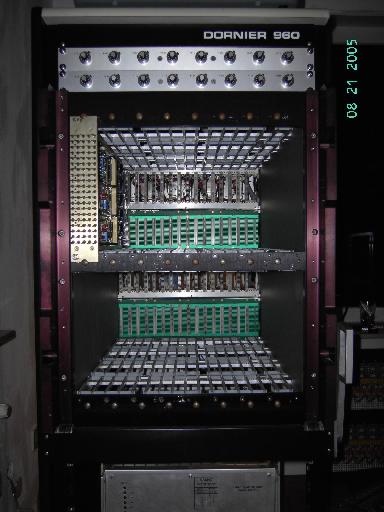
The analog circuitry: The picture below left shows the front of the analog computer with all modules but the one on the very far left removed. The card cage is incredibly deep as can be seen in the picture on the right where the remaining module is shown very clearly. |
|
|
|
|
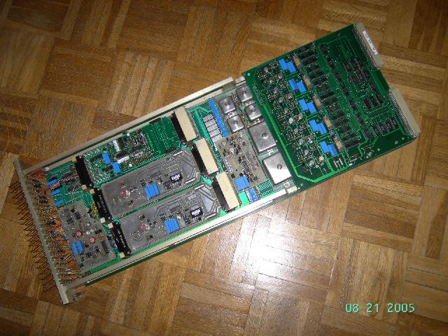
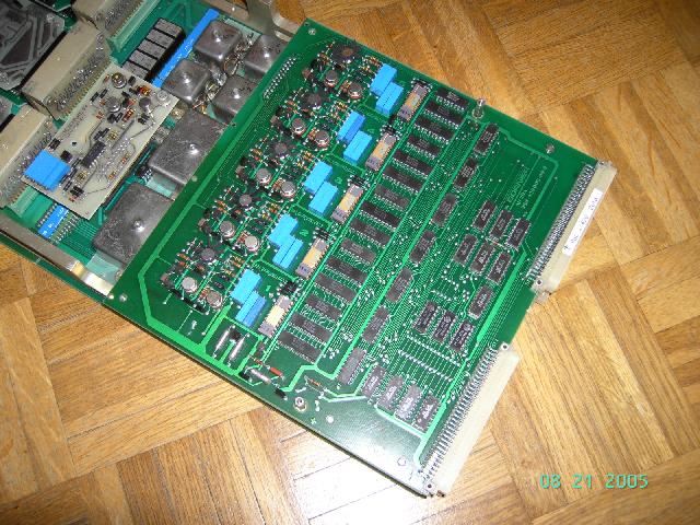
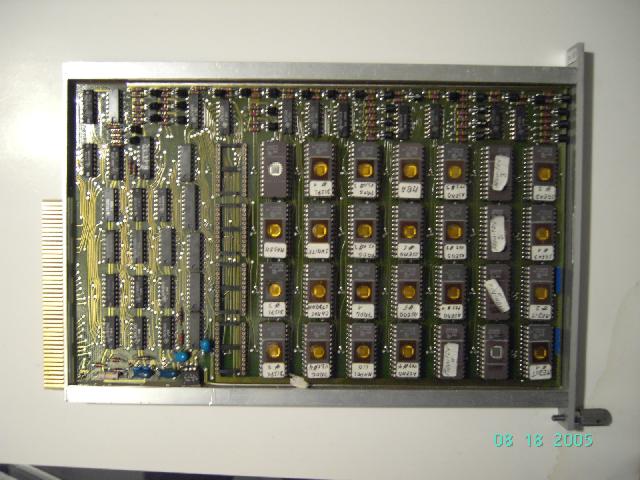
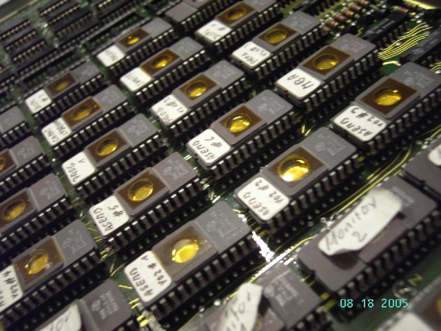
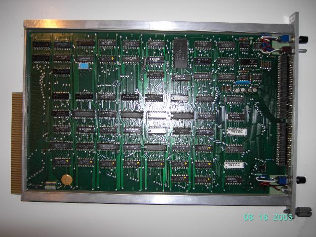
The picture on the left shows one of the up to sixteen analog computing modules which can be plugged into the computer. On the left of the module are the connectors which connect to the plugs on the patch panel. Next to them are the operational amplifiers, limiters, some integrator capacitors, etc. On the right of the module is a piggy back module containing the digital coefficient potentiometers which are shown in more detail in the picture on the right. |
|
|
|
|
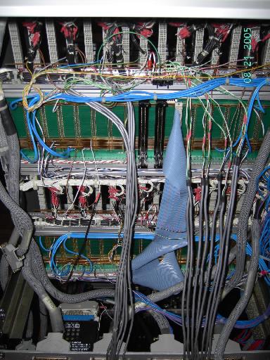
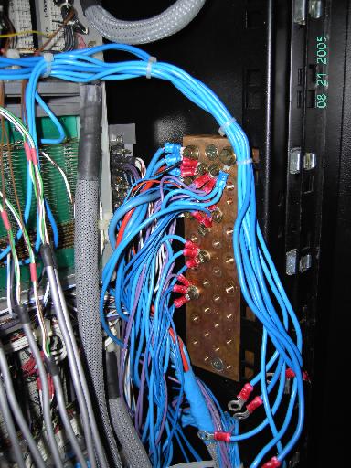
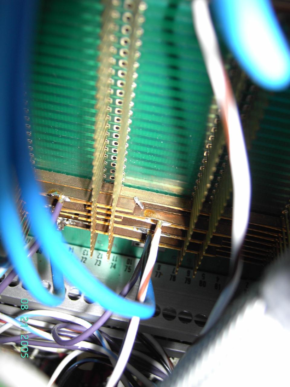
The picture on the left shows the backplane of the analog part of the DO-950. The picture on the right shows the central ground block with some wires still unattached (this picture was taken during the setup of the computer). |
|
|
|
|
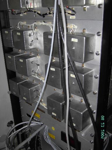
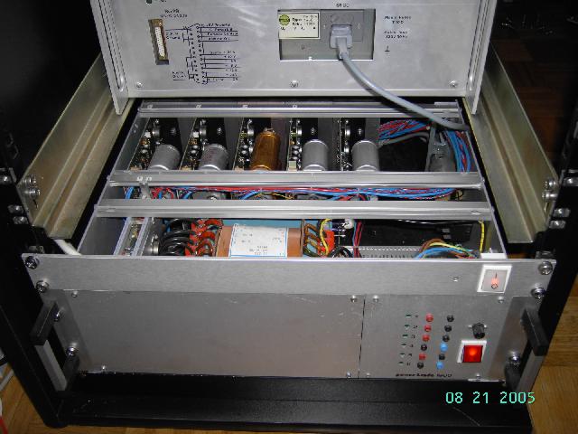
On the left the bank of high precision integrator capacitors can be seen. The picture on the right shows the analog power supply. |
|
|
|
|
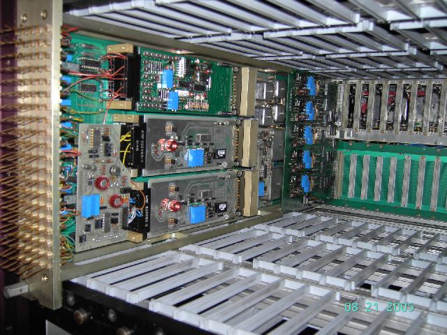
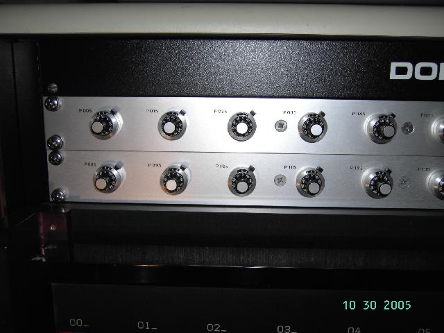
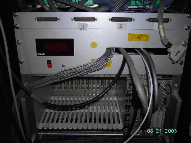
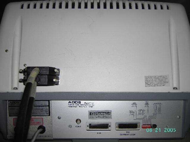
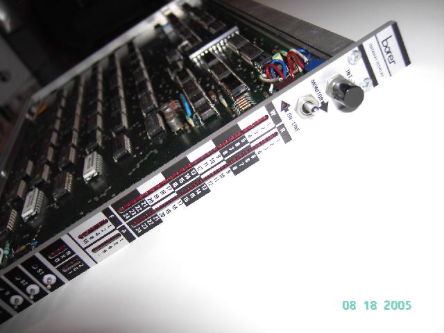
Apart from the already mentioned digital potentiometers the system has sixteen manually settable potentiometers as shown in the picture below left. The picture on the right shows the rear of the system with the CAMAC controller and the associated cabling connecting the analog system with the digital system. |
|
|
|
|
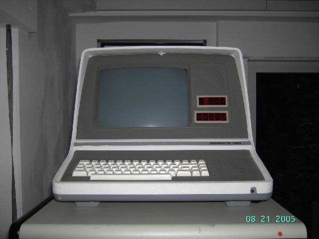
The control terminal of the system can be seen on the left - please note the two seven segment displays on the right side of the terminal. These display the address of a selected component (summer, integrator, potentiometer, limiter, etc.) as well as the voltage at the output of this component. The picture on the right shows the cabling connecting the terminal with the rest of the system. |
|
|
|
|
One of the meanest problems during the setup of the system was an intermittend short circuit between the +/- 10 V lines of the analog part. After hours working with a looking glas I finally found a tiny piece of solder which shorted the +/- 10 V busses. Can you spot it in the picture below? This piece of solder might have come loose during the transport of the system - obviously it has been in the machine for a long time but I seem to be the first one who had any problems with it. |
|
|
|
|
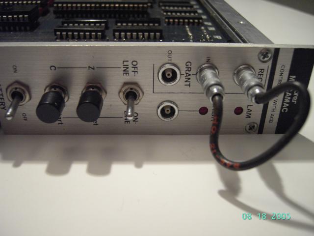
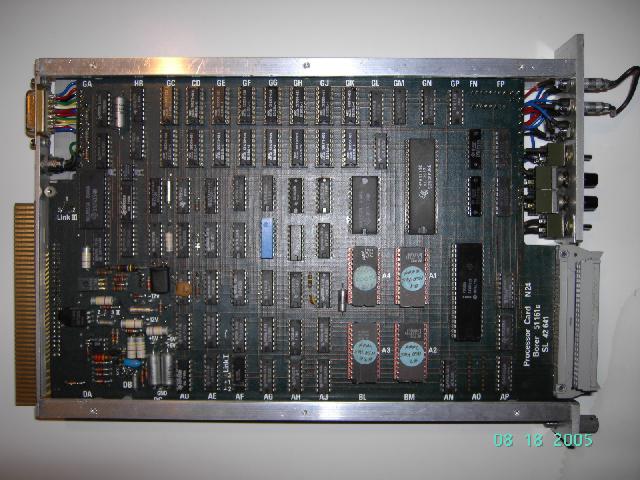
The digital circuitry: The pictures below show the CAMAC controller, called MACAMAC by Dornier. |
|
|
|
|
The ROM board containing the ROMs with the monitor and with the (quite comfortable) BASIC interpreter can be seen below. (I am quite desperately looking for an EPROM programmer capable of reading and writing 2708 type EPROMs since I am afraid that the 2708 EPROMs on this board will loose their contents - the are already about 20 years old.) |
|
|
|
|
A rather interesting device is the CAMAC bus monitor - this device acts as a simple logic analyzer for CAMAC crates. It can display the state of every data, address or control line with LEDs and it can generate interrupts, etc. This board is shown below. |
|
|
|
|
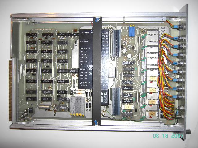
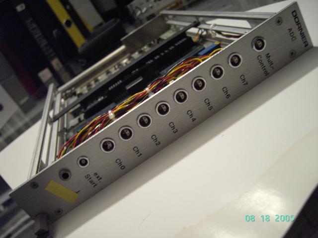
To connect the digital part of the system with the analog part there are some analog to digital converters like the one shown below. These can be read out with simple BASIC statements. |
|
|
|
|
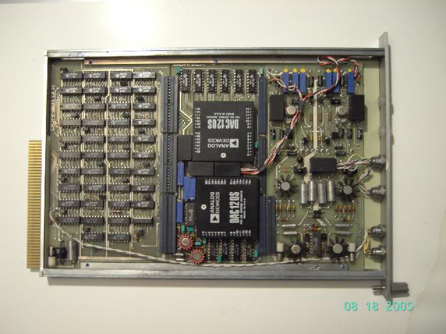
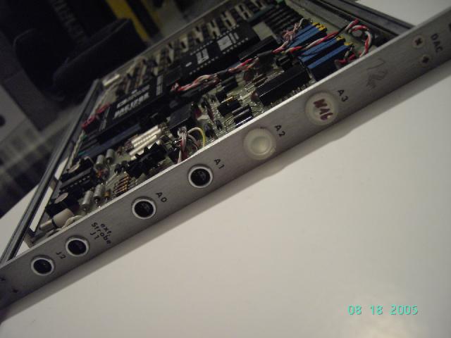
The other way around is done with digital to analog converters like the one shown in the pictures below. |
|
|
|
|
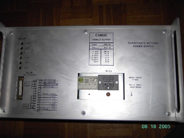
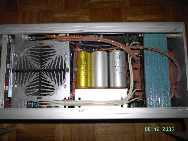
The following two pictures show the rather bulky power supply of the CAMAC crate. This power supply is completely linear and incredibly heavy. In fact it is so heavy that there is a sign warning that the crate should not be carried with the power supply installed! (By the way I wonder how one could carry the crate with the power supply installed. :-) ) |
|
|
|
|
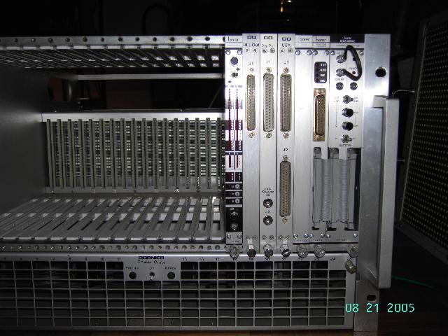
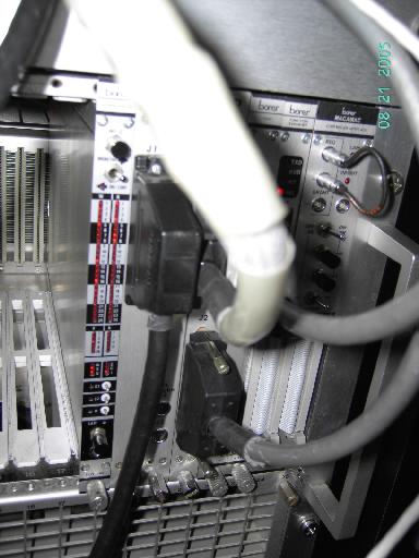
The picture below left shows the CAMAC crate with minimal module population as it was setup for the first dry run without the analog computer. The picture on the right shows the crate with all of the necessary cabling in its natural habitat, i.e. the rear of the DO-960 system. |
|
|
|
|
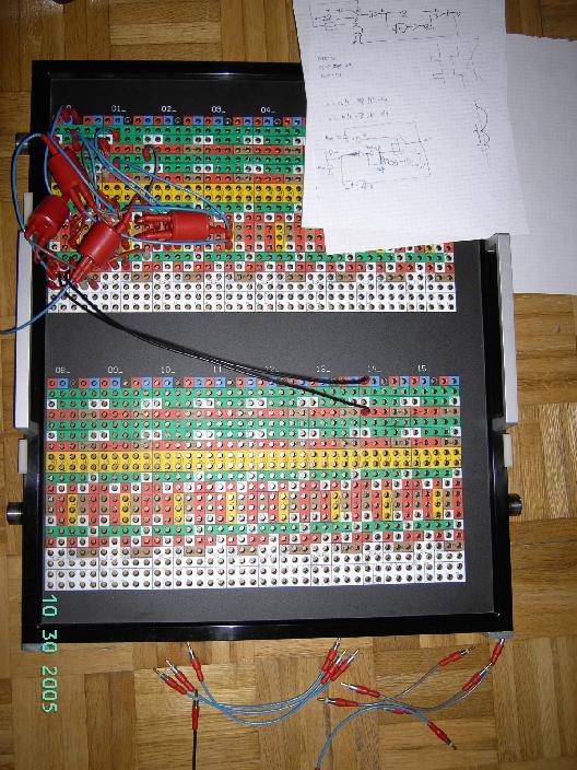
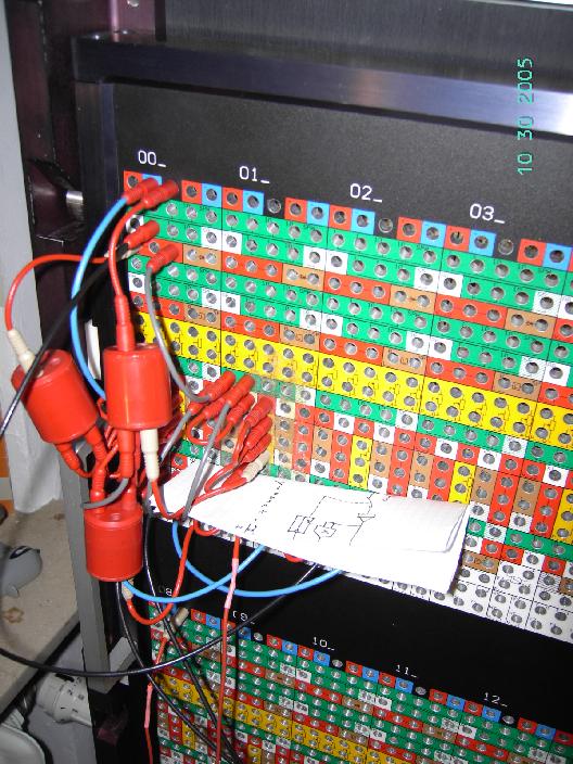
One of the first calculations: One of the first calculations done with this system (apart from the simple harmonic oscillator) was a bouncing ball without friction. The picture below left shows the program panel sitting on the floor during programming (this was done by my friend Ingo Klöckl when he visited me for a weekend - we were programming analog computers all the weekend and it was just wonderful! :-) ). The program, i.e. the basic differential equation of a bouncing ball and its realization as an analog computer program can be seen on the paper in the right upper corner. The picture on the right shows the patch panel in place in the DO-960 with the documentation attached as a piece of paper (good programmers document their code :-) ). |
|
|
|
|
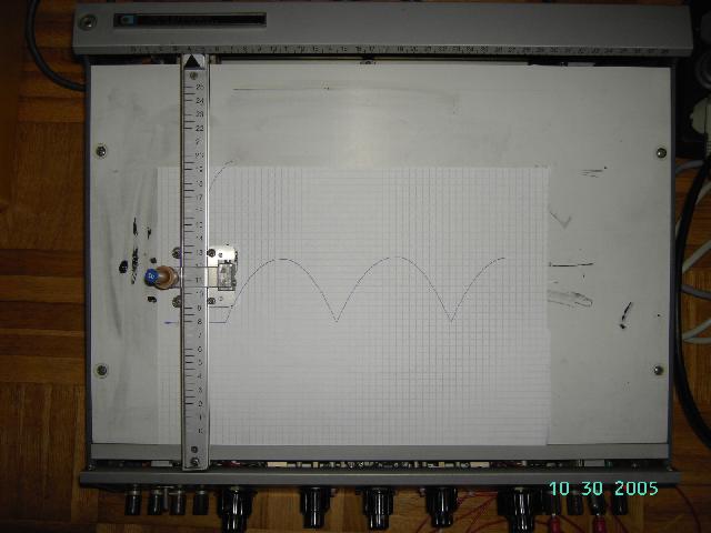
The picture below shows the curve our bouncing ball follows when simulated with our program on the DO-960. The next step would involve some frictional loss of energy and the next step might be a tennis game for two. :-) |
|
|
|
| 19-DEC-2005 |