|
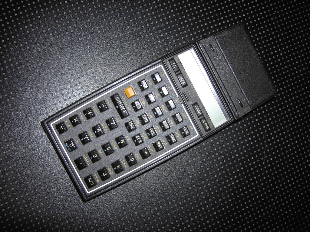
During this year's VCFE which took place in Munich as every year, I had the opportunity to buy a HP 41C programmable calculator in unknown state at the VCFE flea market (I have to give my wife a kiss here since she not only did not complain about the fact that I spent far too much money for very obsolete calculators at the flea market but instead was as happy as I was about the machines we bought - thank you, Rikka, you are truly wonderful!). When I was about 13 or 14 years old I dreamed about the HP 41C since I saw some advertising in long gone magazines, but this calculator was way too expensive for a pupil like me, so I had to dream and to work and play with other calculators. With this in mind, I could not resist buying the HP 41C at the flea market although no one knew if it was working at this time. After some problems getting suitable batteries (Lady cells are quite uncommon on Germany as I had to find out today) I made sure that the battery connectors were not corroded and cleaned those which were before inserting the three batteries just to see that... nothing happened - the calculator did not turn on. |
| Repairing: | |
|
Since I could remember that there were some reported problems concerning the (rather strange) flexible connectors used to connect the two printed circuit boards in the HP 41C I tried to wiggle the case a bit while pressing ON over and over again and suddenly, the calculator displayed "MEMORY LOST"! It turned out that I had to press the lower right part of the calculator to get it working. |
|
|
I decided to open the calculator and have a look if there was anything I could do to fix the problem. To open an HP 41C you first have to remove the rubber feet to gain access to the four screws holding the two halfes of the case together. The top and bottom part are connected by a multi wire flexible connector so they can be easily separated by just pulling the back cover away from the front. |

|
|
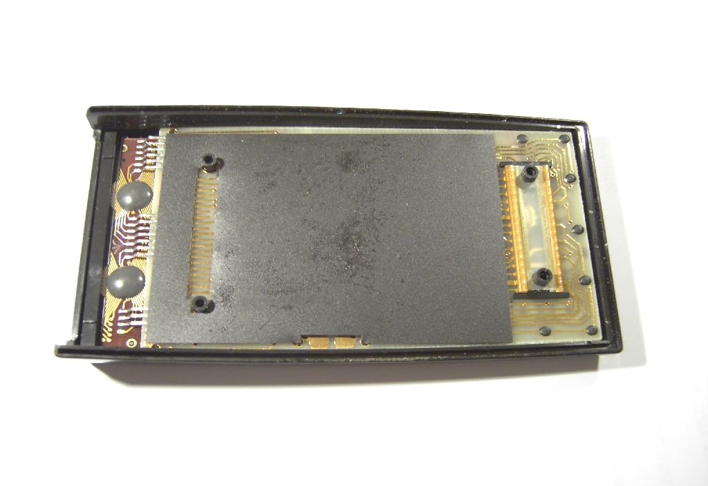
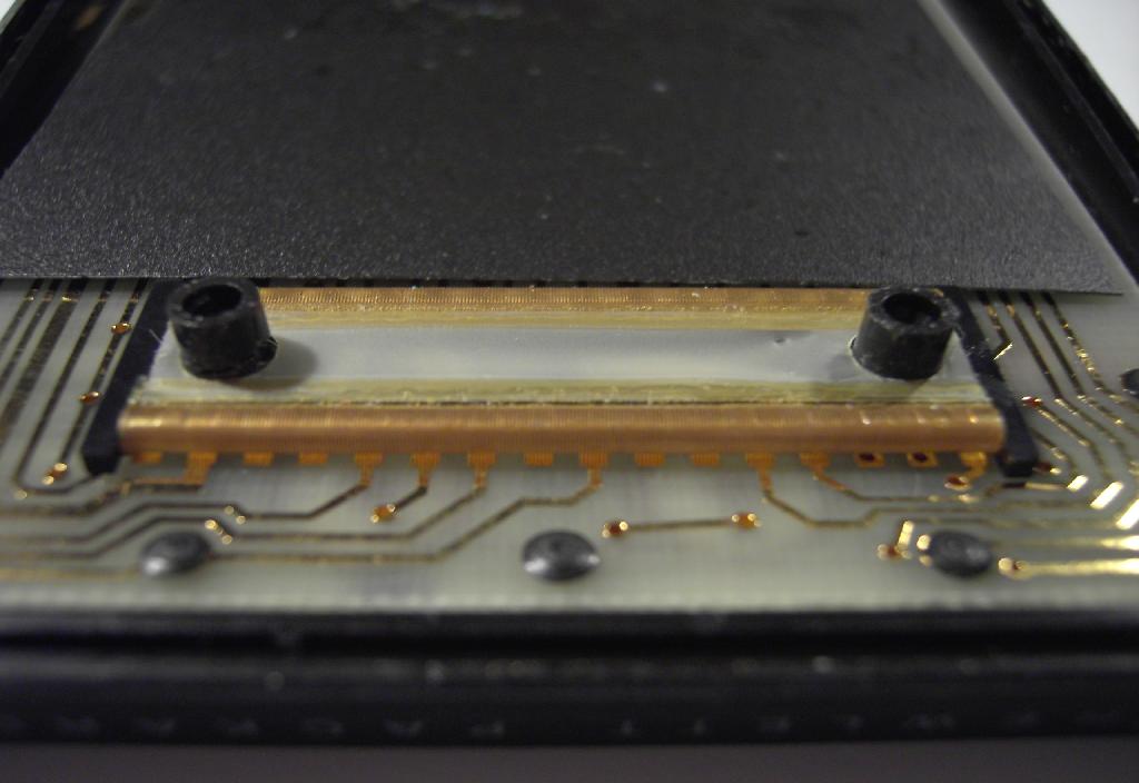
The picture on the left shows the front part of the HP 41C with its CPU-board already removed - normally it sits on the far right aligned by the two black plastic posts holding the flexible connector. |
|
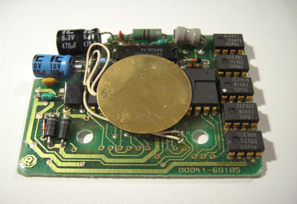
The picture on the right shows the component side of the CPU-board - The large electrolytic capacitor on the top left provides the necessary power to keep the memory alive during battery changes. The CPU-chip is in the middle of the board while the RAM circuits are visible at the far right. |
|
|
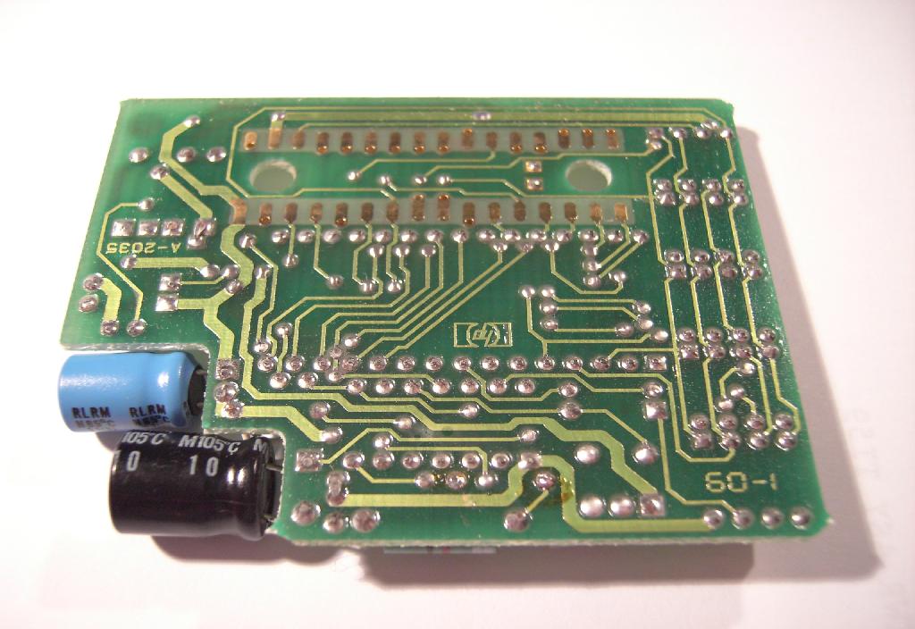
The soldering side of the CPU-board is shown on the left - on top of the picture two rows of 16 connections each can be seen which make contact with the keyboard printed circuit board by means of the flexible connector shown below. |
|
This is the flexible connector strip making contact between the CPU-board and the printed circuit keyboard. This strip is hold in place (as the CPU-board sitting on top of it) by the two black plastic posts on the left and right side. To make a reliable contact some pressure is necessary which is provided by the two screws holding the two halfes of the case in place which fit into these posts. |
|
|
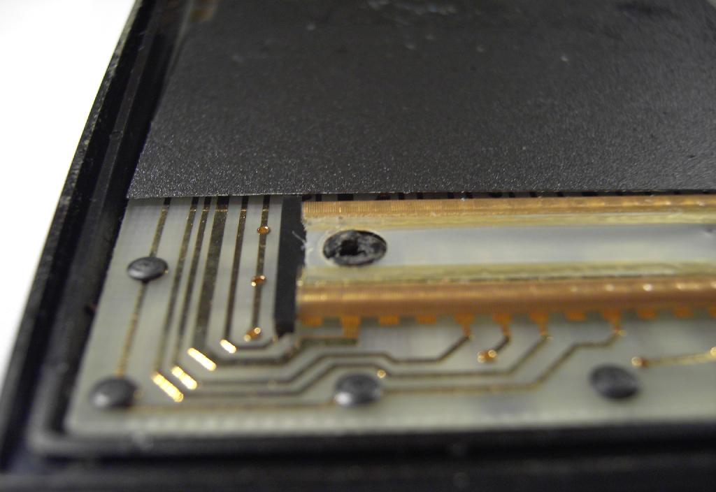
The problem with my HP 41C was the broken post shown in the picture on the left - since it was broken there was not enough pressure on this side of the connector strip to get a reliable contact (in fact, there was no contact at all). The straight forward solution for this would be to rework the post, but I was afraid that it would break again after some years forcing me to repair the HP 41C over and over again. |
|
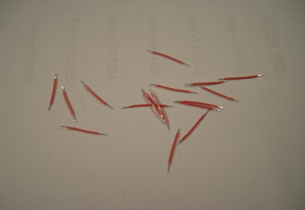
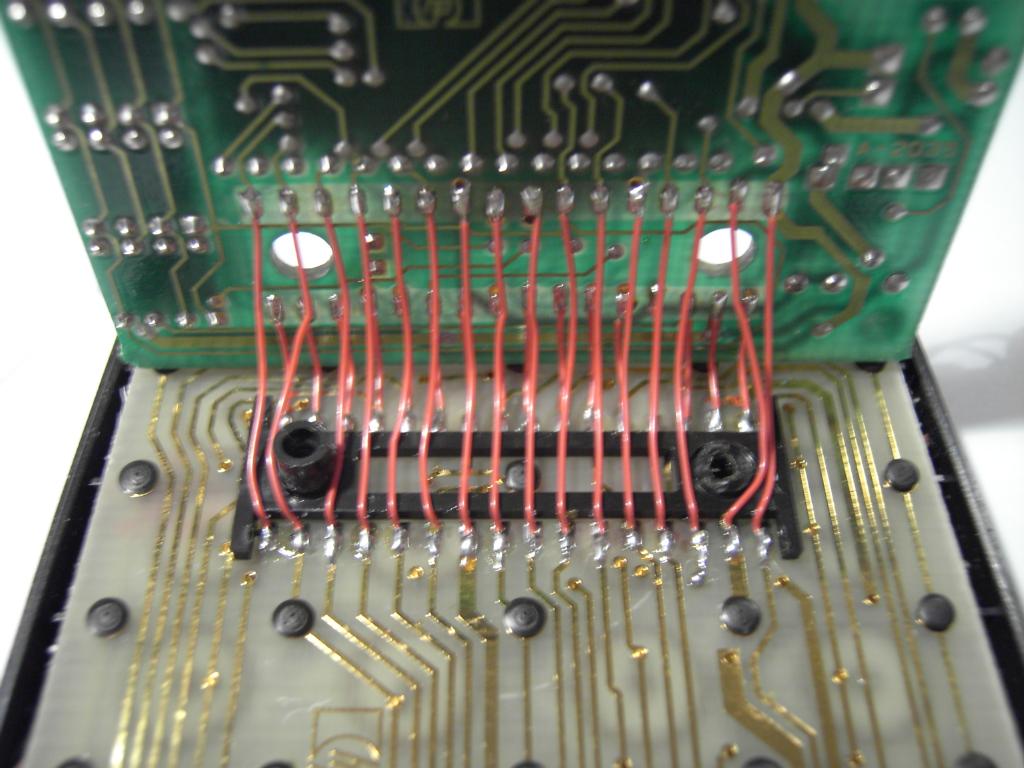
Thus I decided to get rid of the flexible connector strip at all and replace it by 32 thin wires soldered betweend the keyboard and the CPU-board. The first sixteen of these wires can be seen on the right - it is quite crucial for these to be of as exactly the same length as possible to allow proper alignment of the CPU-board after completion of this surgery. |
|
|
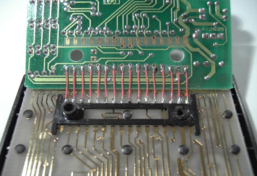
The picture on the left shows the keyboard and the CPU-board after finishing the first row of 16 connections. |
|
The second row of connections is a bit more difficult to solder and the result of this can be seen on the right. |
|

|
After completing all 32 connections I put some isolating tape on the two connector rows of the CPU-board to avoid any intermittent shorts which might be caused by applying pressure to the calculator's case. |
|
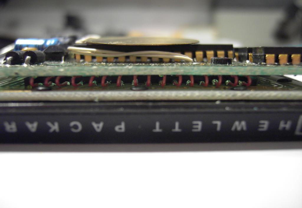
After bending the wires very carefully the picture on the right shows the CPU-board back in place above the keyboard with the first row of wires visible between both PCBs. |
|
|
The calculator worked instantaneously after this surgery and reassembling the case. I know that most collectors of calculators will think of my approach of repairing the HP 41C as blasphemy, but to be honest, I tend to actually use my beloved calculators, so I want to have working machines in my collection to choose from when I think about which one to wear during the day. :-) I have to conclude that it was fairly simple to replace the flexible connector by 32 wires although it took me over an hour to complete the soldering due to the fragile wires (and I had to realize that my eye sight is definitely not improving during time :-) ). If you have an HP 41C which is not working, too, you might consider taking it apart to see if there is a broken plastic post causing bad contacts or no contact at all at one of the large flexible connectors used in the calculator. |
|
| Other resources on the net | |
|
|
|