|
A couple of days ago a friend of mine called (thank you very much, Karl-Heinz!) and told me that he had saved some scrap for me, the institute (a chemistry institute) was about to throw away. When I came there were treasures spread all over the place - a small 68k VME-bus system, lots of Ultrix and OSF-1 documentation and... ...a radio controlled HOPF clock with serial line output which was obviously used to generate a reliabe clock signal for measurement equipment in remote locations. |
Unfortunately, the special HOPF antenna was missing - what a pity. The clock would be a perfect match for FAFNER, my VAX-7820. :-) So I decided to build my own DCF77 antenna. The problem is that the HOPF clock expects an active antenna special made from HOPF - since I had no documentation at all I just had a look with an oscilloscope at the BNC jack in the front plate of the clock. There is only ground and a signal pin connecting the antenna - the signal pin is at +5V and supplies the antenna amplifier. |
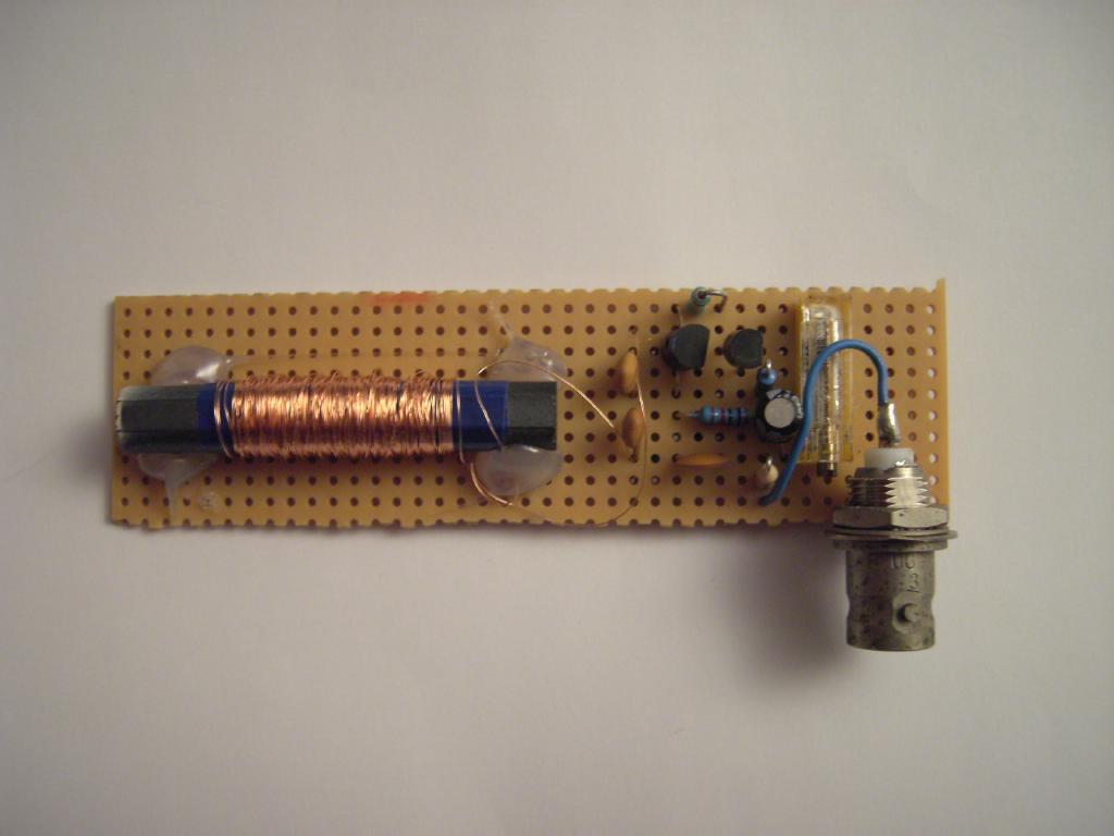
First of all I had to build a simple ferrite antenna - I found an old ferrite rod (I have not the slightest clue where I salvaged this item) and wound about 150 turns of thin wire onto it. Then I built a resonant circuit by paralling this simple antenna with two capacitors. With a square wave generator, an oscillosopce and a frequency counter I tuned this circuit to be resonant at quite exactly 77.5 kHz. This tuned circuit can be seen in the picture of the antenna on the left half of the small circuit board. The capacitors I used turned out to be two capacitors of 2.2nF each in series. |
|
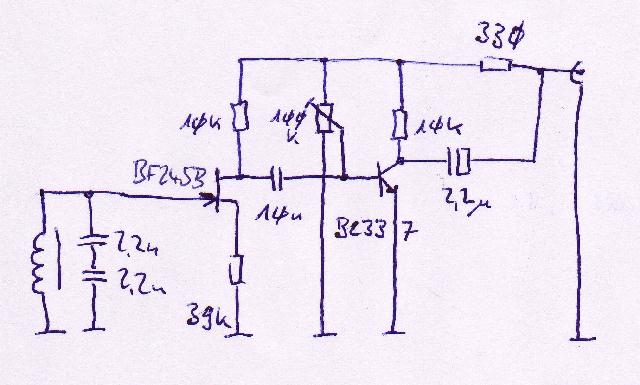
The circuit diagram on the right shows the complete active antenna: Input is via the tuned circuit consisting of the coil wound on the small ferrite rod and the two tuning capacitors. Using this circuit alone I was able to detect the DCF77 signal with about 1 mV amplitude - I am about 80km away from the transmitter which is near Frankfurt. The first amplifier stage contains a BF245B field effect transistor which amplifies and decouples the weak signal obtained from the tuned circuit. |
|
|
The next amplifier stage consists of a common BC337 NPN transistor which is fed with the output signal of the first stage on its basis. This signal is decoupled by a 10 nF capacitor while the operating point is selected with a 10 turn potentiometer. |
The tricky part is the decoupling of the supply voltage and the output signal which is to be sent to the HOPF clock. This is done by modulating the output signal onto the supply voltage. The decoupling takes place using a 2.2 uF capacitor while the rest of the circuit is connected to the supply voltage by a 330 Ohm resistor. (By the way - it is a good idea to filter the supply voltage after this resistor with a 10 uF capacitor or the like which is not shown in this drawing.) |
|
On November 24th, 2009, I got a mail from Noud with the following improvement on the (way too simple) circuit above: (1) Regarding your BF245B stage - put a good Ld in series at Vdd in front of Rd (< Rd//Rs). ( @ 77.5kHz::: <8kOhm, so say 4kOhm: Ld = 8.2 [mH]) - put some matching (resonant at 77.5kHz) Cs parallel also from the Rs towards Vss. Cs = 513 [pF] (2) Then "the trick" - Route from Vdd to Ld a single turn (or two...) around the ferrite rod in a second coil (co-coupled) with the input coil. This provides positive feedback, that can neutralize ferrite losses completely. (But beware of oscillations!, suppress with less turns, or R, or C). Result: serious signal gain! |
|
|
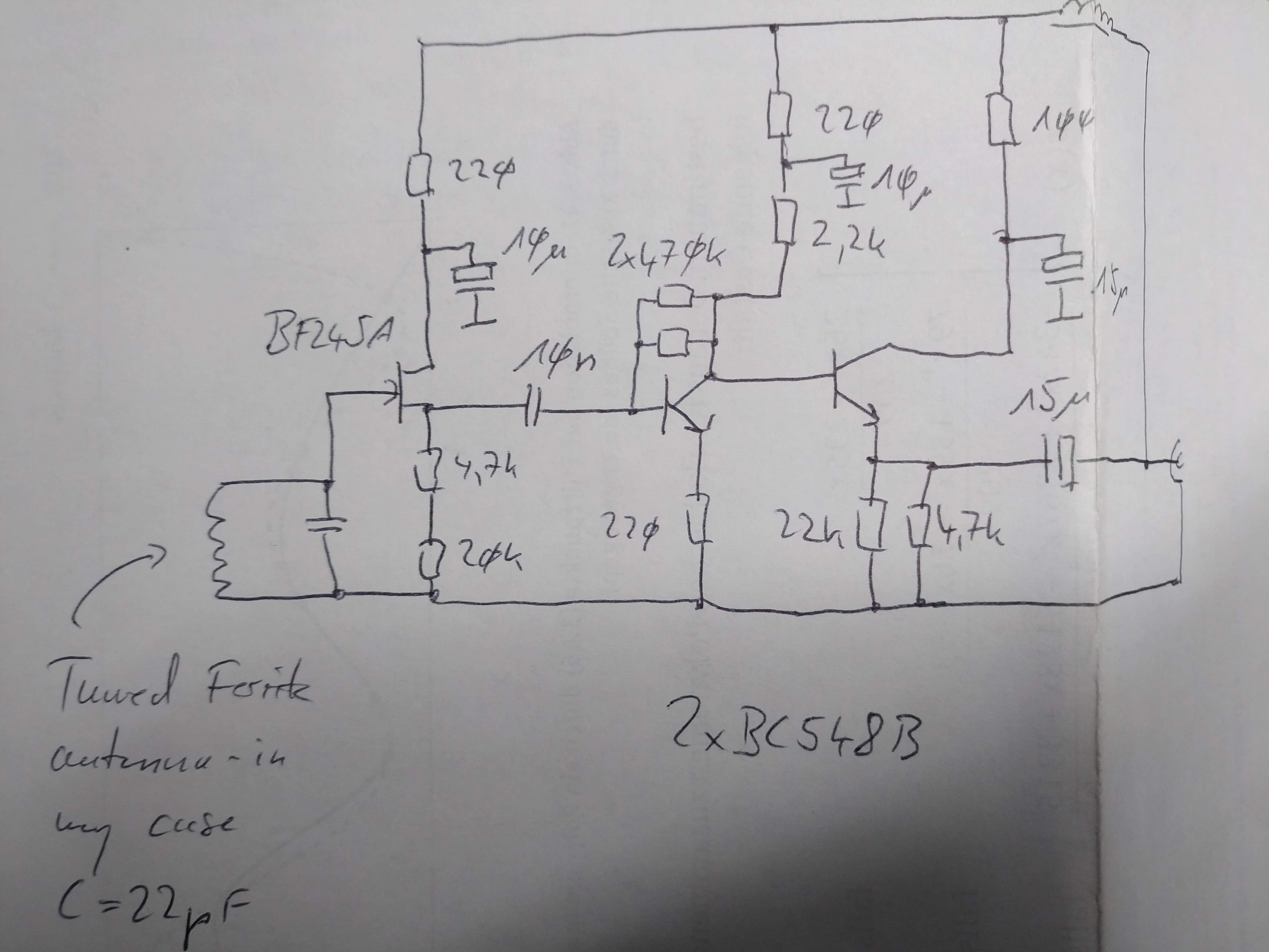
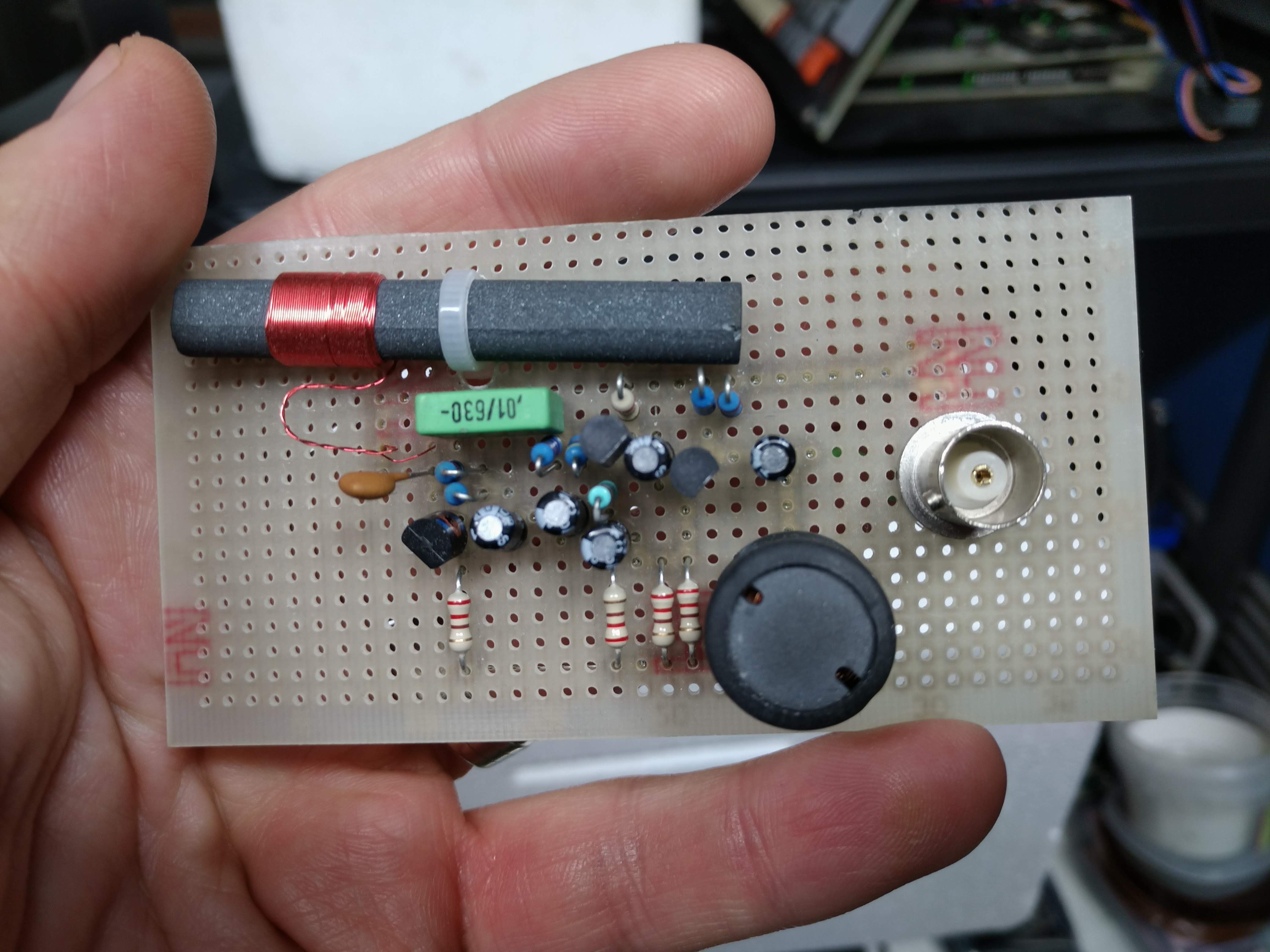
In 2014 I started over and made a new active antenna which has since been in service and performs really well. The schematic and resulting circuit are shown below - the coil shown in the upper right of the schematic is not critical and only has too make sure that the supply voltage is free of any HF signals. The strange series and parallel resistor circuits were due to the fact that I had to do with whatever resistors I had at hand. :-) |
|
|
|