|
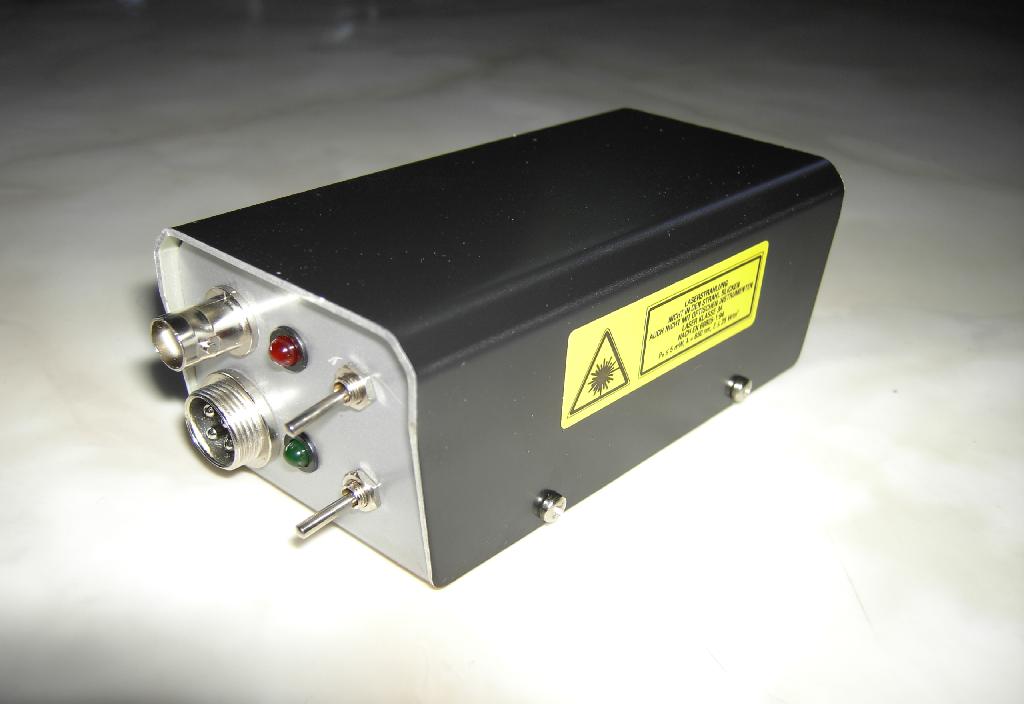
When I was out for a walk with my wife I began thinking about measuring distances using a modulated laser (this was triggered by the beautiful view we had from the top of a hill we climbed). When we came back home I immediately had a look in my pile of scrap and found enough to build a simple TTL modulated diode laser for first experiments. This device will be described in the following. The completed device can be seen above. |
| Circuit: | |
|
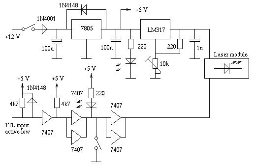
The circuit I created (see above) is very simple and does not need many explanations. The first part consists of a fixed voltage regulator 7805 to derive a stable +5 V source. This is followed by a LM317 adjustable voltage regulator since the diode laser module I found in my spare parts requires exactly 3 V - everything above this will kill the module immediately. Since I want to be able to modulate the laser beam by a TTL input signal, the circuit contains a 7607 non-inverting open collector driver IC which controls the laser module. The TTL input stage has a simple diode to protect the 7407 if a positive input voltage larger than +5 V is applied to the input jack. |
|
| Construction: | |
|
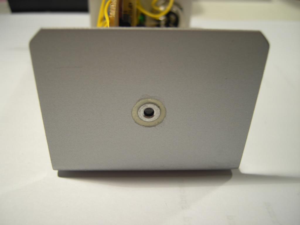
The picture on the right shows the front plate of the completed device. In the middle the laser diode module is visible which I glued into the metal enclosure by epoxyd glue. This was necessary since the frame of the diode module is at +3 V potential while the outer metal enclosure is at ground potential, so it is necessary to insulate the diode module from the frame. |
|
|
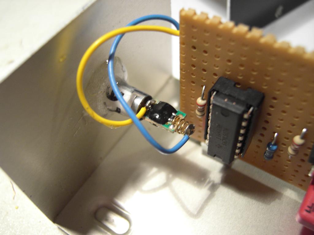
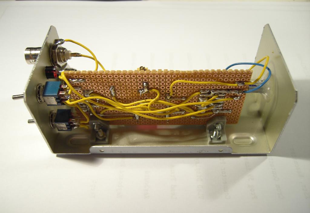
On the left the laser diode module can be seen which was originally part of a cheap laser pointer. The blue wire is ground while the yellow wire is +3 V. To the right of the module the 7407 driver can be seen. |
|
The picture on the right shows the component side of the circuit board I built. On the far right the 7805 voltage regulator can be seen while the LM317 is located left to the yellow ten turn potentiometer which is used to adjust the +3 V supply. The driver circuit 7407 is on the far left. |

|
|
The picture on the left shows the soldering side of the circuit board. |
|
The rear side of the completed device can be seen in the picture on the right. The four pole connector on the lower left side is the power connector - the BNC connector on the upper left is the TTL input for the modulator circuit. The green LED will be lit when power is on (this is controlled by the switch on the lower right) while the red LED will be lit when the laser beam is on. Switching the laser beam on is performed by either toggling the switch on the upper right or by applying a low level TTL signal to the BNC jack. |

|
| Safety tips: | |
|
First of all, I do not take any responsibility for any damages resulting from attempts to recreate this circuit. You are completely responsible for your actions yourself. Whenever you work with a laser, even with a low power device like this laser pointer module, be extremely careful! Wear safety goggles which are suited for the laser's frequency. Never ever look into the beam - neither directly nor indirectly. Laser diode (modules) are extremely sensitive and will be damaged immediately by static electricity and/or over voltage/current. Do not connect the laser diode (module) to the circuit before you are sure that the +3 V regulator really supplies +3 V! |
|