|
A couple of weeks ago I was lucky and bought a wonderful Fluke 8300A digital voltmeter in an online auction for only 18 EUR. Since Fluke had a habit for using unusual power jacks, the seller was unable to test the device and so I expected to get something wich would need some repair (I love repairing old electronic devices :-) ). It turned out that I rather underestimated the efforts necessary to get this device up and running again (but it was lots of fun for 18 EUR :-) ). |
| Reparing the device: | |
|
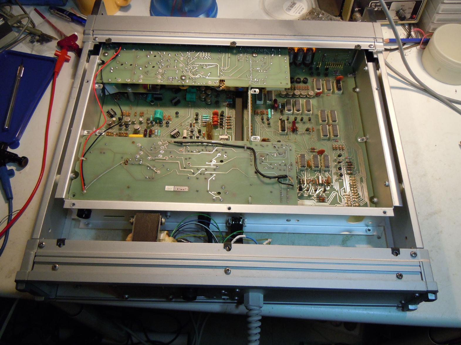
Since I did not have a suitable power cable for this device I decided to install a fixed power cord which turned out to be fairly simple since this particular Fluke 8300A did not have the digital readout and remote control features installed, so about half of its back cover was empty and I used this space for the new power cord which can be seen in the picture on the right in the bottom middle. Using this new power cord, I switched the device on for the first time since I got it (using an isolating transformer, of course). What happened? Nothing - the display did not light, but on the other hand no smoke, no dying electrolytic capacitors, so it could have been worse. |
|
|
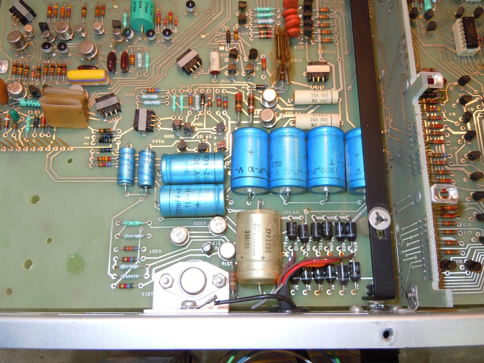
The great thing about Fluke is not only that they made and make just wonderful instruments, but they still have all of the manuals available for download on their pages, so it was fairly easy to find the schematics for my Fluke 8300A (which was built in 1972 - isn't this great? A company that still has their schematics of devices being nearly 40 years old available for download! Have you ever tried to get a schematic for your washing machine? This is next to impossible...). With the aid of these schematics it turned out to be rather easy to debug the faulty power supply - the driver transistor for the linear power transistor was defective. All of this applied to the +18 V part of the power supply which is shown in the picture on the left. Since +18 V serve as a reference and supply for nearly everything else, all other voltages, which were missing before, came back in an instant after replacing the faulty transistor. |
|
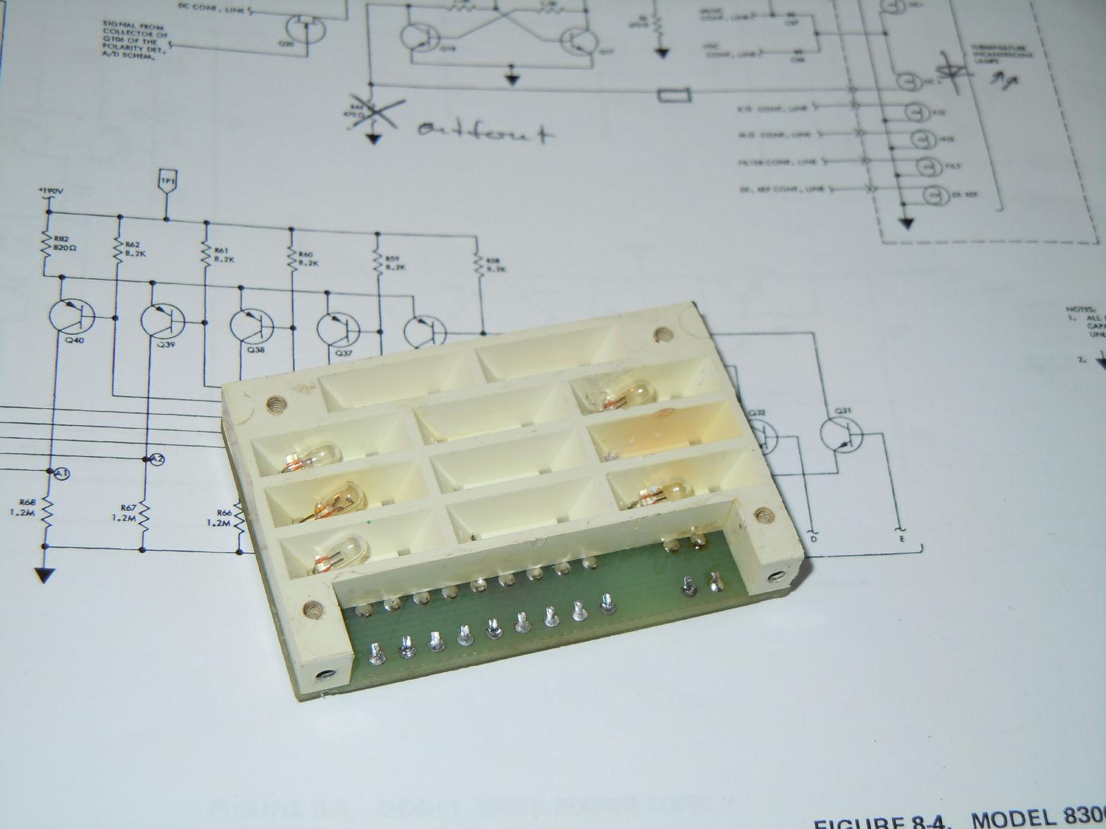
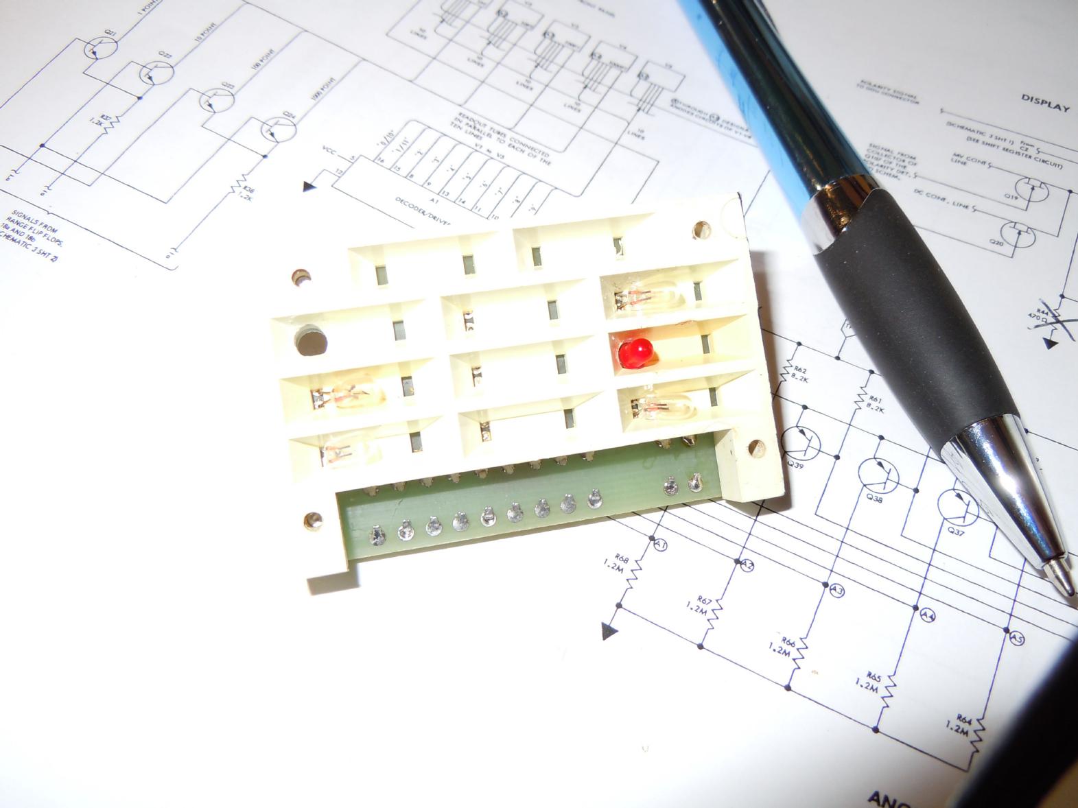
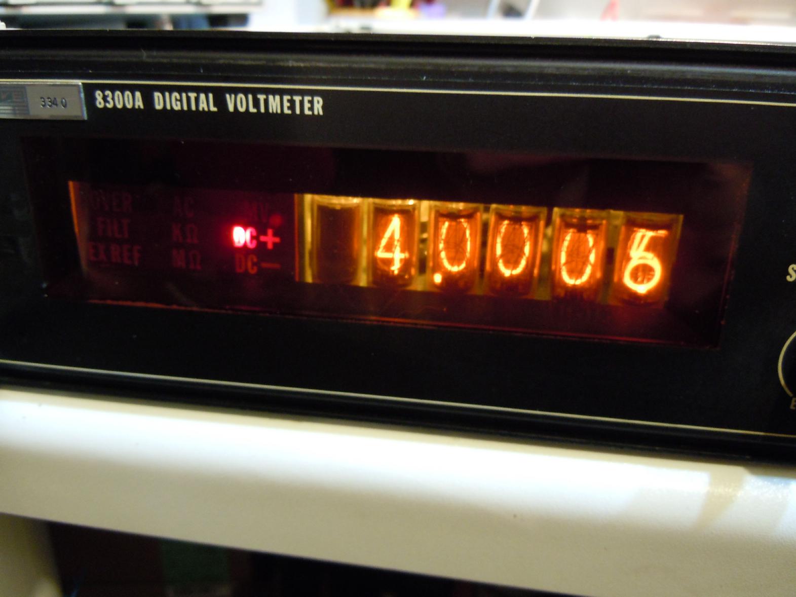
The instrument itself seemed to be working quite well, but what did not work were most of the indicator incandescent lamps. These are mounted in a quite delicate plastic block attached to a printed circuit board with very (very!) tiny holes for the leads of the incredibly small (and defective) lamps. Since I neither had such lamps at hand nor did I want to use these, I decided to replace the faulty lamps with red 3mm LEDs. The picture below left shows my (quite horrible) modification to the status indicator enclosure - I drilled through the plastic and the circuit board to make enough room for a 3mm LED to fit in. The next step involved removing some 470 Ohm resistors which were previously used to make sure that even lamps that were not brightly lit were heated by a base current. This current was high enough for the LEDs to be lit even when they were supposed to be switched off. The picture below right shows the resulting display - the "DC +" is clearly readable although the LED produces a much smaller spot of light than the previously installed lamp. |
|
|
|
|
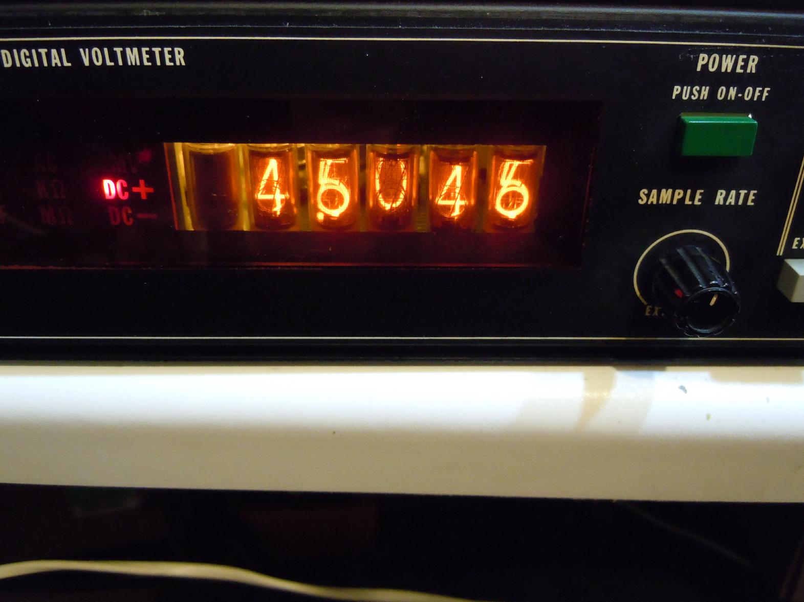
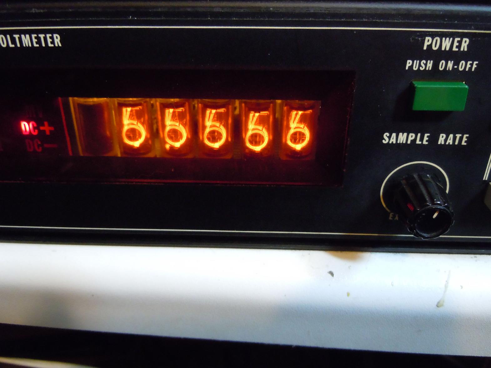
Fixing the next problem took me a bit longer. Every time when a digit 5 or 6 should have been displayed, both digits were lit simultaneously. I have to admit that I have been quite stupid in this case since I first suspected an error in the driving stages involving a 7441 decoder and its surrounding circuitry. Only after some time I had the idea to remove the 7441 and replace it by an IC socket which I could use to permanently select individual digits. This can be seen in the picture below left. The piece of wire shorts the pins 12 (GND) and 11 thus enabling the digit 6 of the Nixie tubes. The result is visible in the picture below right - all tubes display two digits simultaneously. |

|
|
|
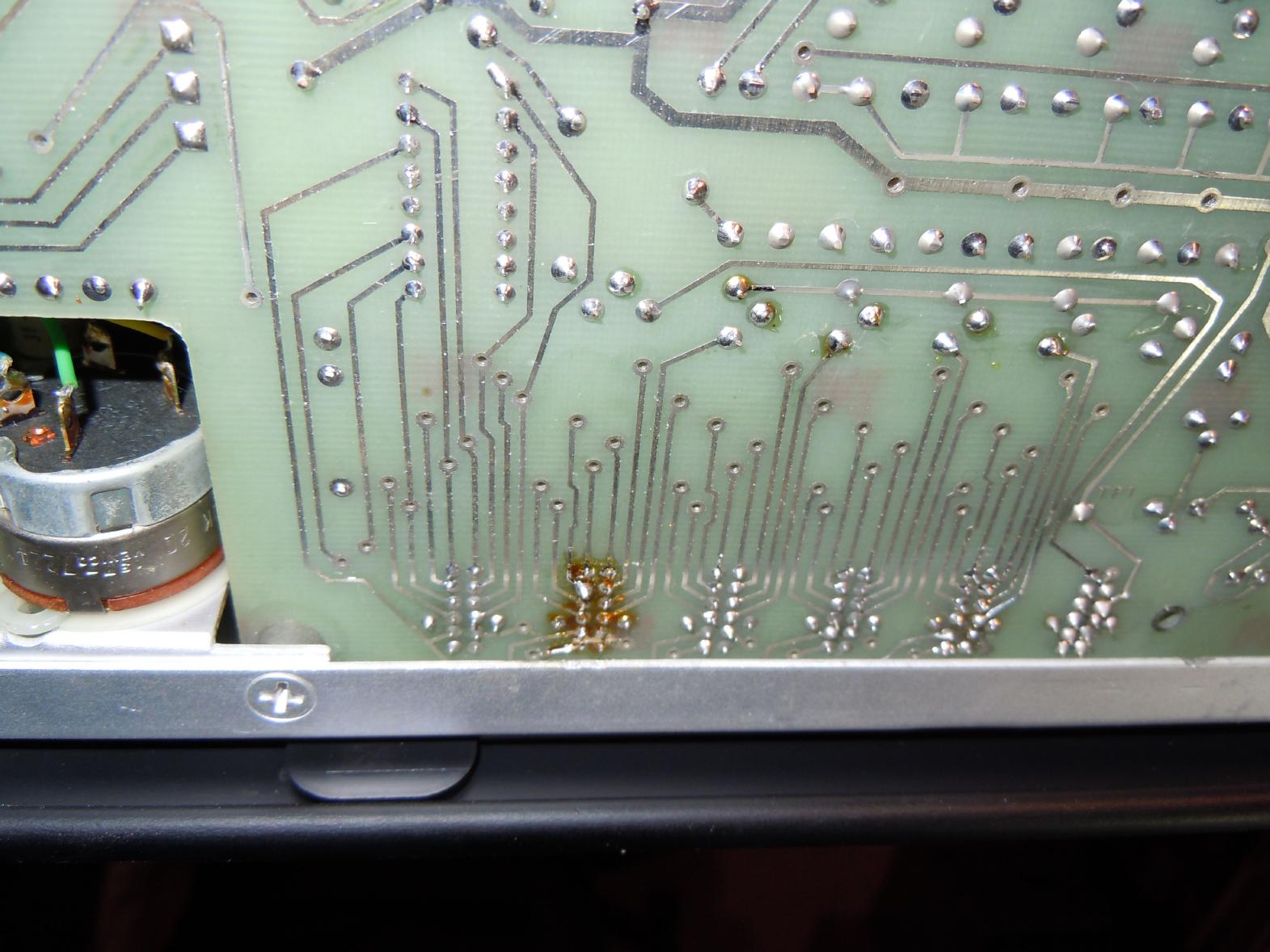
Thus it was clear that the fault was somewhere located in the Nixie tubes themselves or their surroundings. After removing some mounting material I saw that one of the tubes already had been replace some time ago. Of course, I suspected a short in this area but using an Ohm meter nothing was to be found. No shorts, nothing... I was puzzled. Only after some minutes I remembered having seen strange things in conjunction with excess Colophonium in high voltage circuits many years ago. Believe it or not, but cleaning the dark area below the replaced tube cured the problem once and for all. |
|
|
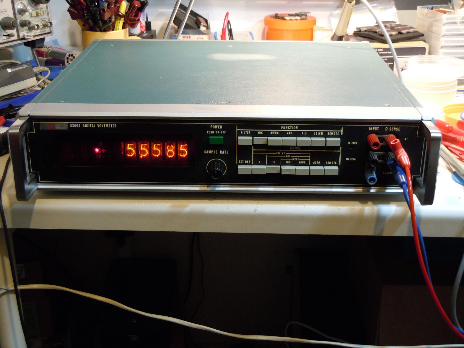
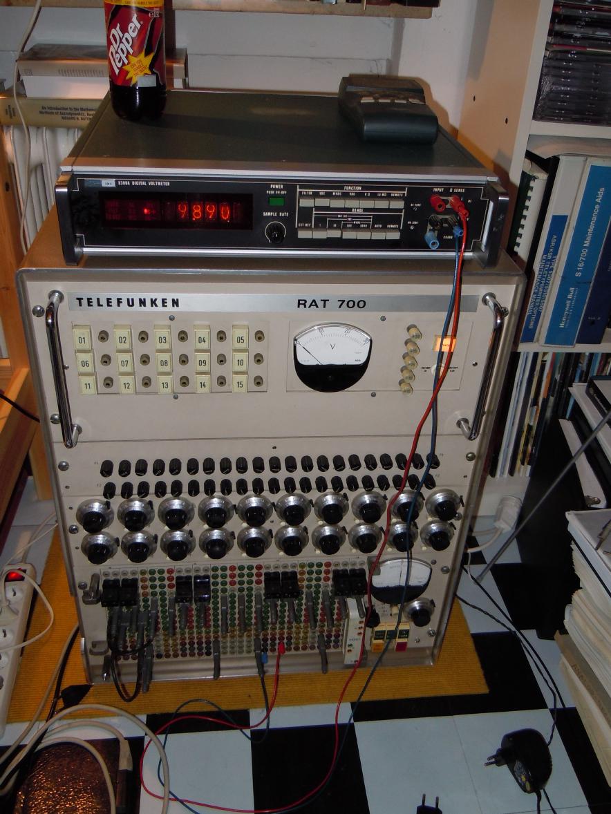
Some initial tests with a simple calibrator showed that the instrument was still within its specifications (after 38 years!) and I placed it on top of one of my Telefunken RAT 700 table top analog computers where I will use it as precision read out instrument. The picture on the left shows the voltmeter in its new setup. Unfortunately this pictures shows something else: The least significant digit is not working! *ARGL* I thought that I had found and corrected all faults, but this right most digit quit working only after a couple of minutes of using the instrument. Back to the workbench again (it is no fun to open the instrument - the top and bottom cover are held in place by six screws each. Below these two additional covers are found which are held by five additional screws each. In addition to that the buffer board must be removed (two screws) which is a bit tricky since it has a lot of pins and some fixed cables attached to it...) - after measuring signal forms in the Nixie driving circuitry it turned out that the first stage driver of the right most digit had died. Replacing it with a BFY 43 transistor cured the problem - all digits are now working again and I really do hope that the instrument will now work without further assistance for next 40 years. :-) |