|
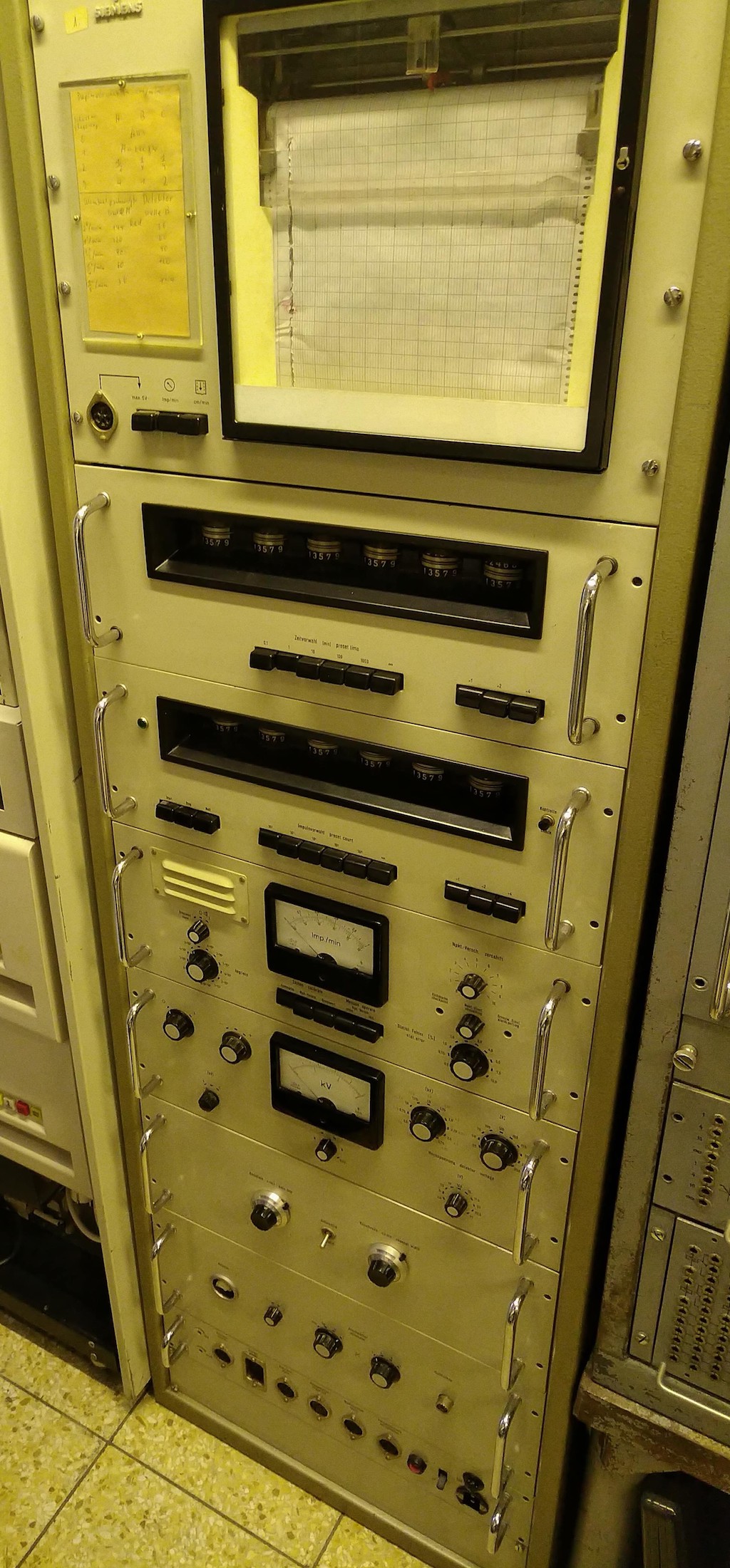
A couple of weeks ago I got a gamma spectrometer made by Siemens, probably in the late 1950s/early 1960s. I had seen this instrument long ago when I was still in school. Back then the father of a friend of mine, an electronics enthusiast, saved this wonderful machine from being scrapped. I can remember being fascinated by this system and was as happy as can be when I was offerd to take it under my wings - the next generation caretaker. :-) The picture on the left shows the system after it arrived at my home and had been cleaned as it was rather dirty from standing in a (fortunately dry) cellar room for some decades. From bottom (!) to top, the system consists of the following units:
It turned out to be a rather complex debugging and restoration process as every unit had its own share of problems as will be described in the following. |
|
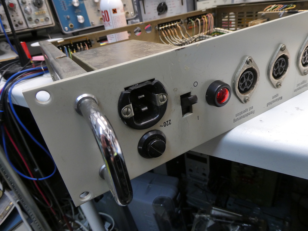
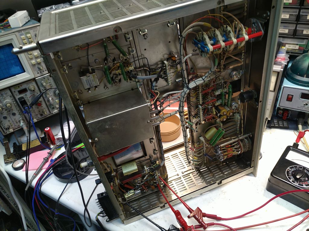
The first thing that was apparent was the rather sad state of the cabling of the three fans at the back of the rack as can be seen on the right. The cables had extremely deteriorated during the last couple of decades and had to be replaced which was not difficult but a bit tedious. The insulation of the replaced cables literally crumbled at touch. The next unit to take of of was the power distribution unit which basically contains the mains input, a mains switch, fuse, mains filter, much cabling for the front connectors and a small power supply which controls a relay which is used in conjunction with an optional external plotter. |
|
|
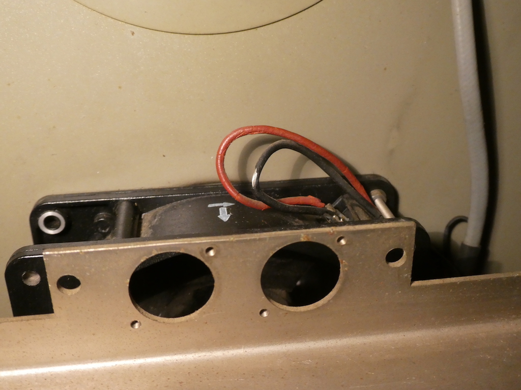
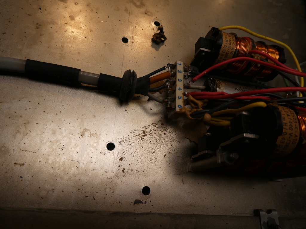
The three pictures below show the basic problems the power distribution unit had: The mains connector was broken - fortunately, I had an exact matching part in my stock. Further, all of the mains filter capacitors had more or less exploded in the past. What really amazes me is that these did not cause a short. These capacitors have been removed and replacements are on order - at the moment, the system runs without the filter. These filter capacitors were also used in some of the units and were all in similar states of decomposition. Some had already exploded and had spit out molten wax and bitumen over the surrounding circuitry. All of these were removed as well in the following steps. |
|
|
|
|
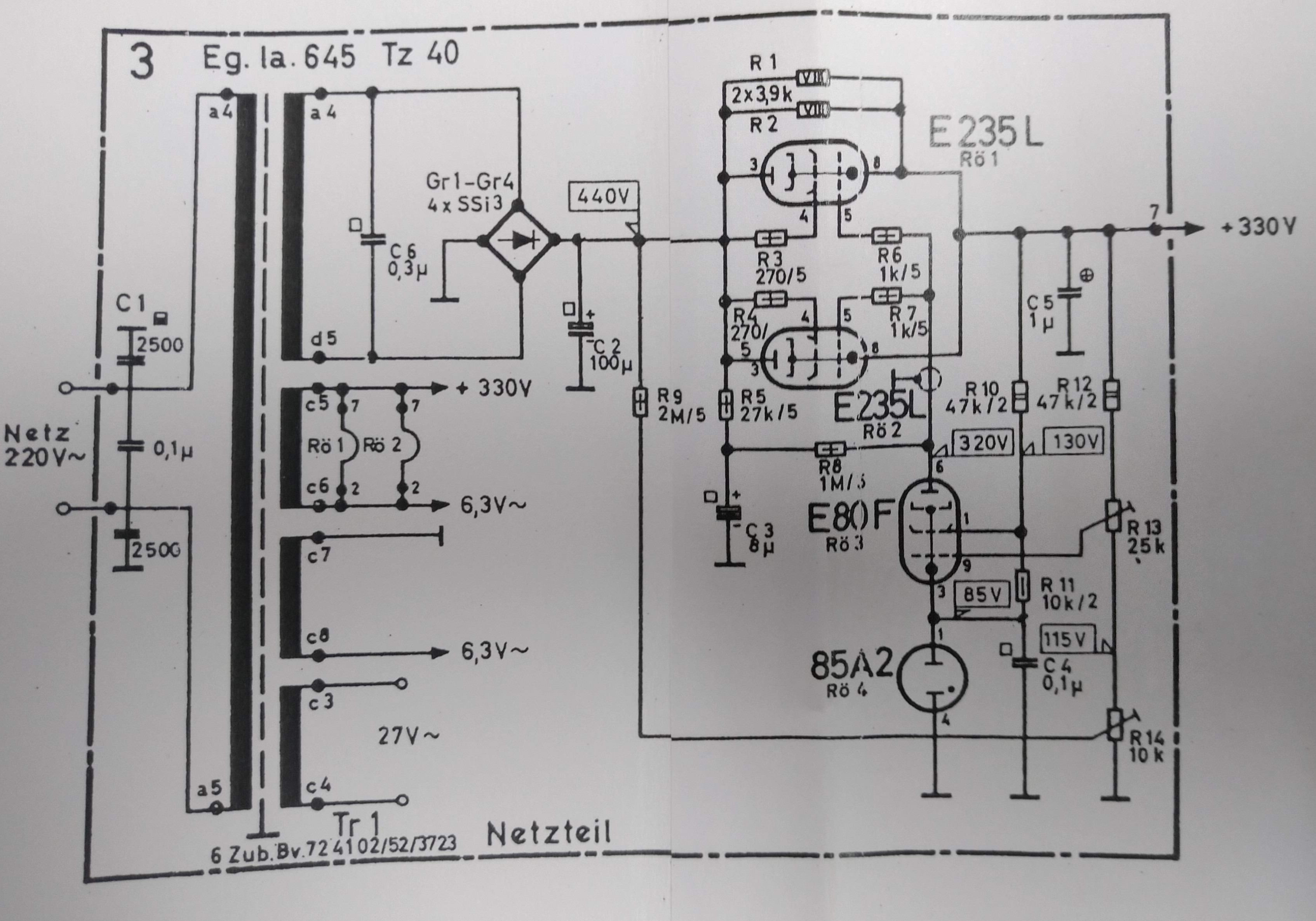
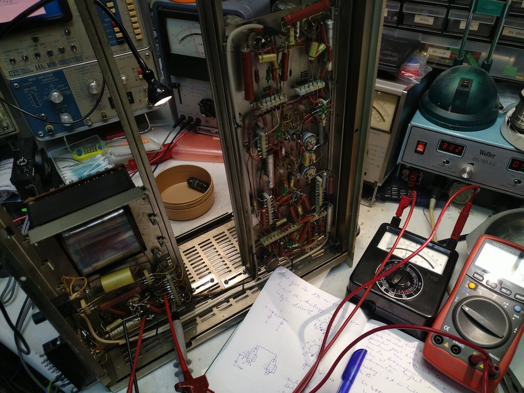
It was now that things got interesting as I had no schematics, no documentation, nothing at all about the system. Fortunately, this changed during the restoration project thanks to my friend Bernd Johann who also has one of these spectrometers in his collection (with the motor variable discriminator - I am quite jealous :-) ) and also has a documentation set which he copied and sent me. Without this, the repair would have been next to impossible as the circuitry is quite intricate in some units, especially the counter/clock combination with their crosswise control capabilities. The next unit on the workbench was the input amplifier which had quite a number of problems. First of all, some of the wiring was completely charred. These wires were replaced by Teflon insulated wires of which I had a short length left from a past project. Next, I changed the settings of the magnetic voltage regulators for the tube heaters so that even with todays 235 V AC they will be heated with 6.3 V AC. The linear regulated power supply was a bit more tricky. At first I had to do without any schematics. The circuit itself is pretty straight forward: A 85A2 stabilizing tube yields a reference voltage which is then fed to a small pentode which drives the control grid of the E235L power pentode. |
|
|
|
|
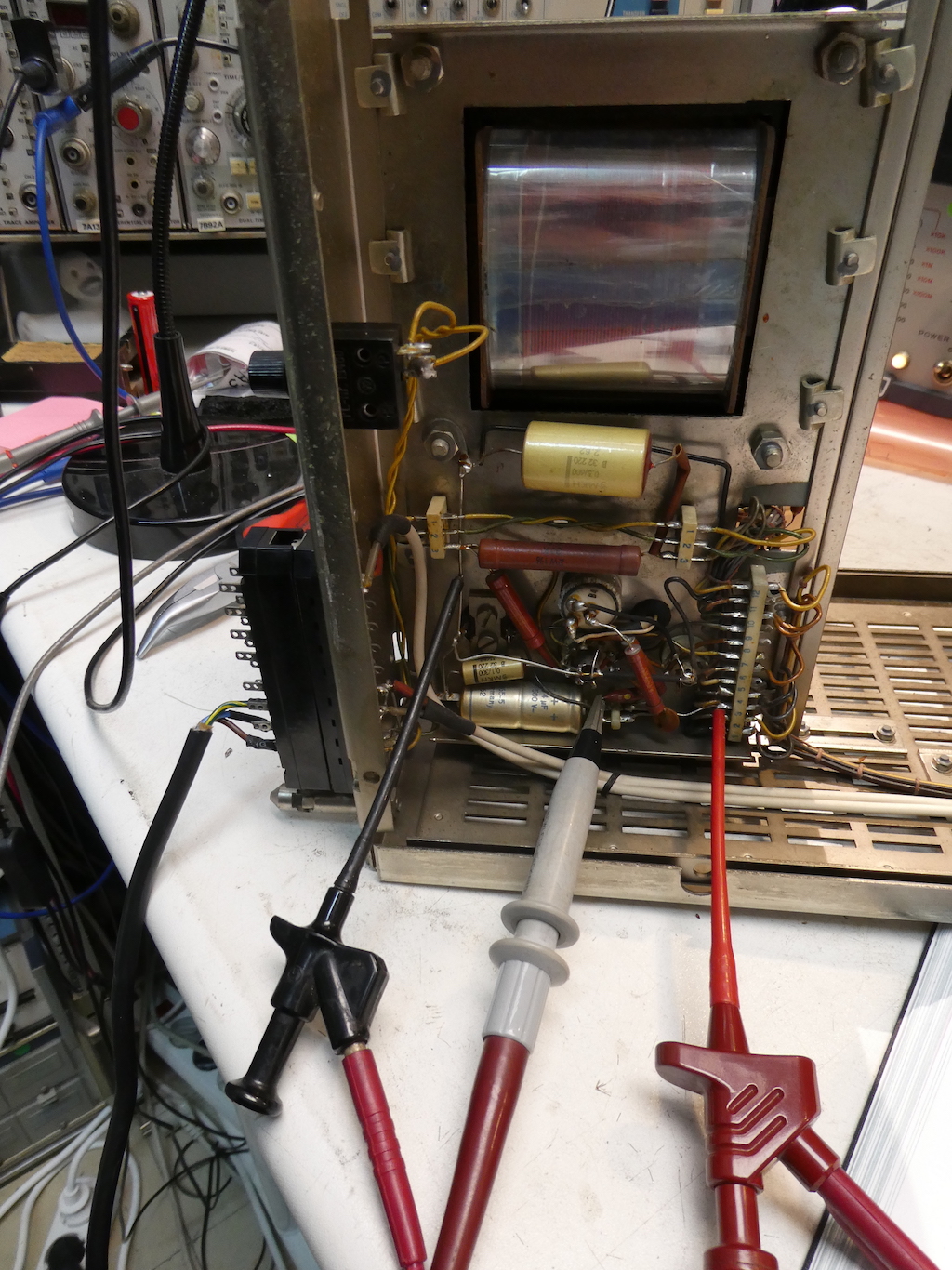
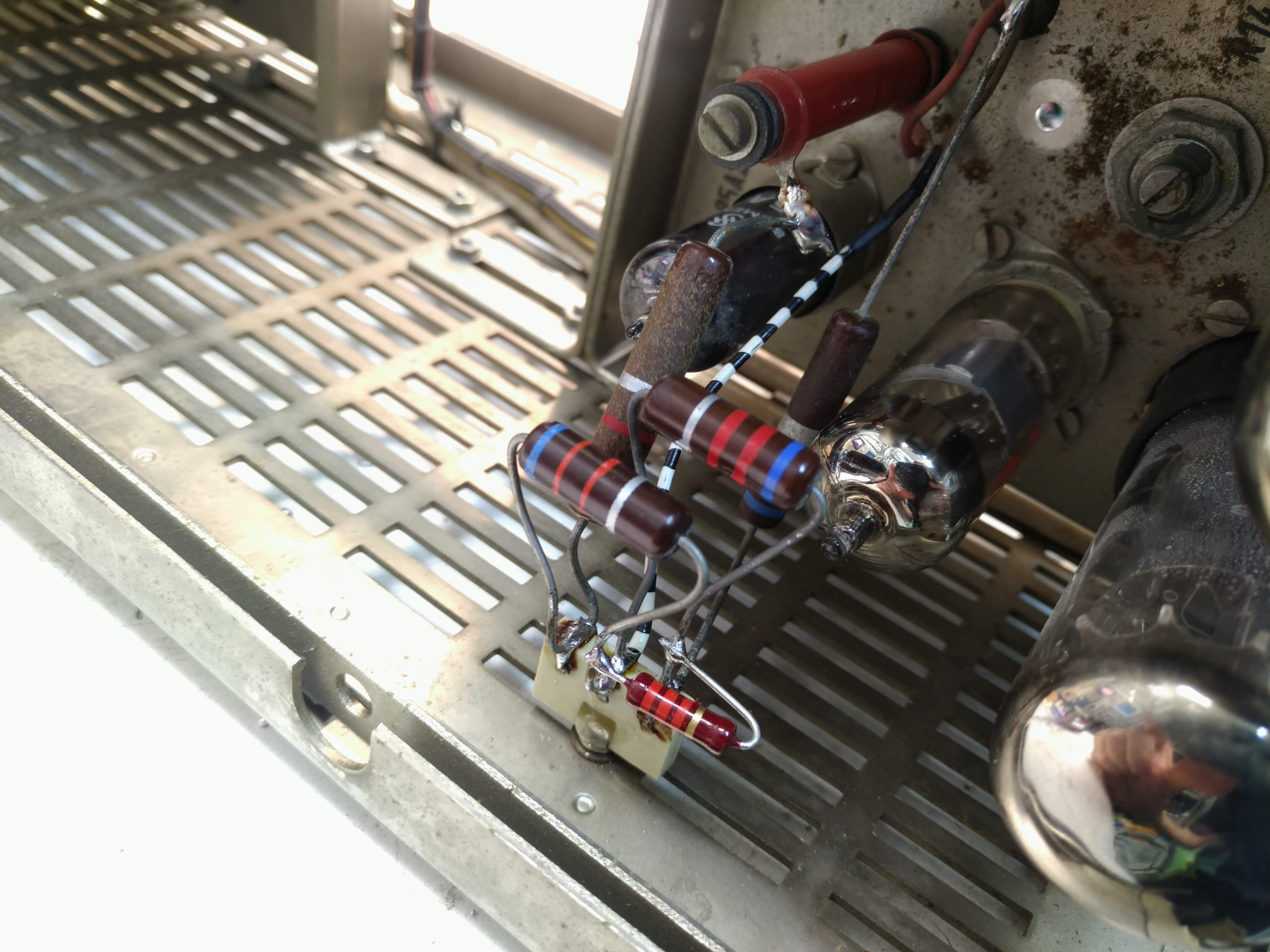
It turned out that the power supply just did not stabilize its output voltage at all. One of the causes was directly visible: The stabilizer tube did not fire so that there was no stabilized reference voltage at all. Fortunately, I had a replacement tube of the correct type in my stock. Alas, even after replacing it, the power supply still did not regulate its output voltage. Quickly it became clear that the central potentiometer connected to the control grid of the small-signal pentode E80F was defective. Its slider made no contact at all. Since it could not be repaired and I did not have a suitable replacement part in my stock, I decided to replace it by a (not too clever) combination of fixed resistors to get the desired output voltage. Since I did not have any schematics at first, I had no way to know what the correct output voltage would be. After some quick calculations I decided, given the plate resistors I saw in the remaining circuitry, that 285 V would be a decent output voltage, which I set accordingly with my resistor contraption. When I got the schematics it became clear that the correct output voltage of this particular power supply is 330 V which I corrected in due course. The picture in the middle above shows the back sided of the power supply section during repair and the working power supply in the right picture. Isn't the glow of the stabilizing tube shown in the picture on the right above just beautiful? |
|
The picture on the right shows one of my resistor contraptions to replace the failed 25k potentiometer R13 in the schematic above. It was a bit fiddly to find a resistor combination to replace the potentiometer in order to get the correct supply voltage. The constraints were the series resistance that should be close to 25k Ohms, and the fact that I don't have that many resistors in my stock which allow 2W and more of load. The resistors were mounted on a contemporary three contact ceramic strip which was screwed to the side panel of the unit. |
|
|
The picture on the left shows the first two units of the system mounted in the rack and powered on. There is a never-ending debate on how to deal with old capacitors. Many people tend to "recap" everything in sight just to be on the safe side. This is, of course, a valid option, but I, personally, try to keep as many of the original parts as possible and I really hate it to replace something just because it is old. Accordingly, I do some basic checks on the capacitors (capacitance and ESR) and then run the individual units for a prolonged time on the workbench while closely monitoring it. Only one of the electrolytic capacitors of the system failed after several hours. This was in the power supply of the discriminator and immediately blew the fuse of this unit, so no harm was done. |
|
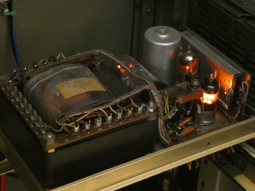
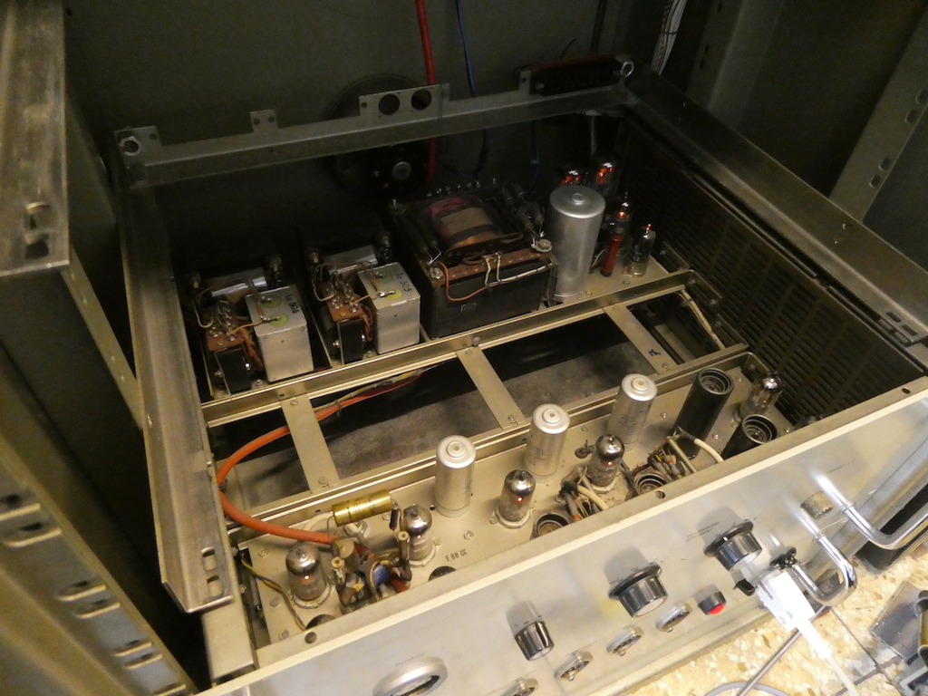
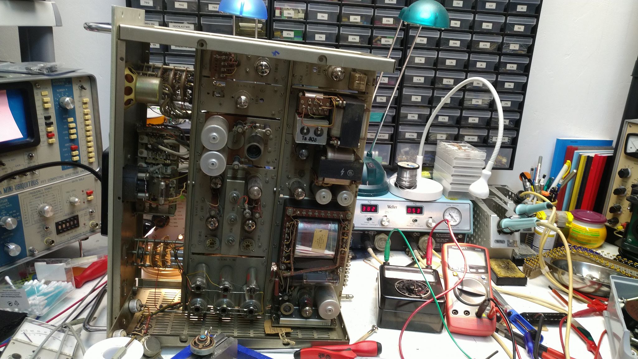
The picture on the right shows the top of the input amplifier chassis. The construction of all the modules of this system is pretty remarkable as they are fully modular with small, medium and large units mounted on a common chassis and interconnected by cable trees. This makes debugging quite straight-forward and pleasing. The sub-chassis in the back holds (from left to right) two magnetic voltage stabilizers for the tube heaters. Both of these have been adapted to 235 V by changing some of the bridges on top of the two transformers. The right half of the sub-chassis in the back holds the main power supply for this unit with its large transformer, the large cylindrical electrolytic capacitor, two power pentodes E235L (back right), a small-signal pentode E80F, and yet again a 85A2 voltage stabilizer tube. The area in the middle is unpopulated, and the front sub-chassis holds the cascaded amplifier stages. The tubes are all long-life tubes, mostly E88CC and E288CC but also pentodes in some output stages etc. The red cable is a double insulated high-voltage cable that runs from the high voltage connector on the front panel to the high voltage power supply mounted two slots atop of this amplifier unit. |
|
|
The picture on the left shows a bottom view of the discriminator unit which is mounted directly above the input amplifier. It, too, had a blown mains filter capacitor and - pretty incredibly - also a defective voltage stabilizer tube 85A2 and a defective voltage divider potentiometer. Apart from this, the discriminator worked fine until its electrolytic capacitor in the power supply blew after a couple of hours, which was easy to fix. The discriminator receives impulses from the input amplifier and yields an output pulse only if the input pulse is either above a certain threshold ("integrating" mode) or between a threshold and an upper limit ("differential" mode). Since this model lacks the motor unit, base and limit are set manually by means of two precision potentiometers. Currently, it is run with minimum threshold and in integrating mode so that every impulse from the amplifier is routed through to the counter and the arithmetic mean unit. |
|
The picture on the right shows the discriminator mounted in the chassis above the input amplifier and the power distribution unit. The rear part again contains the stabilized power supply which is simpler than that of the input amplifier as it does not contain a stabilized heater supply. The power supply uses only a single E235L pentode instead of the two parallel tubes in the amplifier unit. The potentiometer on the left is used to set the threshold voltage while that on the right sets the upper limit which is added to the threshold and can be as large as 30 V. The switch located between both potentiometers selects between differential and integral mode of operation. |

|
|
The high voltage supply, shown on the left, was the easiest unit to fix as only the output voltage of the power supply had to be readjusted and the stabilized 6.3 V AC had to be tweaked a bit to work with our 235 V mains. The design is pretty straight-forward: The high voltage is derived from a high-frequency oscillator driving a step-up-transformer with several filter stages following the high voltage rectifiers on its secondary. The power supply section is a bit tricky as it consists of three independent power supplies: One stabilizes the heater voltages, a secónd one yields the central plate voltage of 300 V, and a third one yields a highly-stabilized reference voltage which is used by the HV regulator. The supply has two modes of operation, yielding either an output voltage of up to 3 kV or up to 5 kV with switch selectable polarity depending on the type of detector used. |
|
The next unit, which allows the readout of a mean value as well as acoustic output, was pretty challenging to get up and running again. Apart from the "normal" problems with the power supply (exploded mains filter capacitor, voltages out of range) it had a cracked tube E88CC which acts as the loudspeaker driver. Thanks to my friend Matt I had a replacement for that in stock. Feeding the unit with an external signal to see if it works showed that the meter needle was either at the far left or far right of the scale, bouncing violently from one side to the other. As I am quite paranoid when it comes to old meters, I decided to add clamping diodes over the meter coil which turned out to be a good idea. When I tried to adjust the zero-setting-potentiometer it turned out that the meter needle could not be moved to zero at all. Only the two extremes at the left and right could be "set". After thinking about this for some time, it turned out that the wire-wound zero-setting-potentiometer had its wire corroded and broken in two places! At first I tried to replace the potentiometer but due to its rather unusual shape could not find a suitable part in my stock... Since my beloved wife Rikka and I bought a binocular microscope last year, I decided to try to repair the broken wire which worked after some failed attempts. The potentiometer now has two tiny "bumps" where I soldered the wire ends together but works quite well.
|
|
|
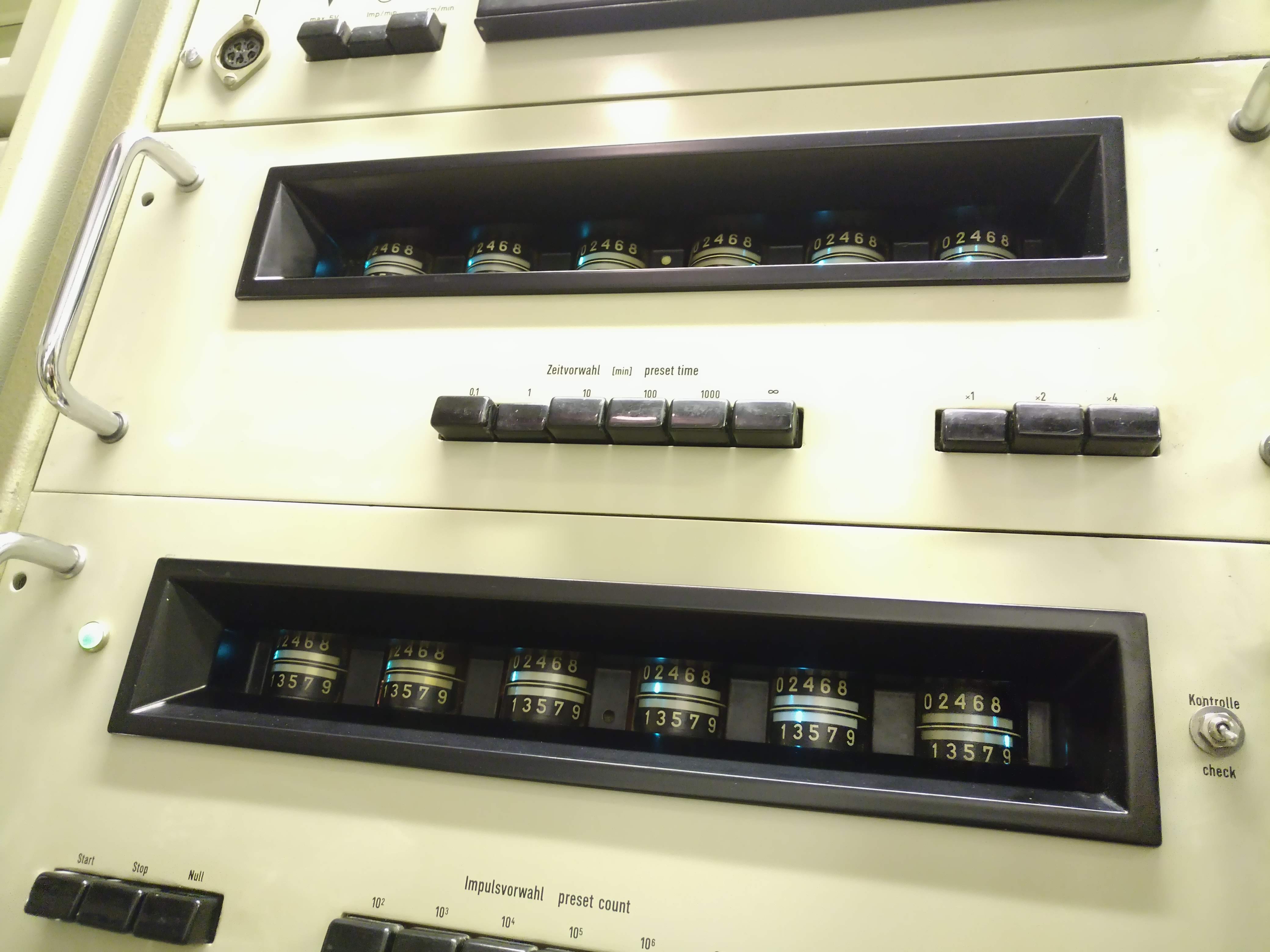
The timer/counter section of this gamma spectrometer is just beautiful and a work of art! The counters are based on the rare E1T tube. This tube basically implements a decade counter with a carry output so that they can be cascaded. Since our time system is unfortunately not decimal in its very nature, the timer unit which sits on top of the counter is clocked by a 1.6667 kHz quartz crystal! The rightmost tube counts 1/100 minutes, followed by 1/10 minutes etc. to the left. The system basically allows two modes of operation: It can either count events for a predetermined time frame such as a minute or it can determina the time interval required to reach a predetermined number of counts. In either case the counting operation stops when the end condition is met and the result(s) can be read out either from the tubes or electronically using the connectors at the power distribution panel mounted on the bottom of the rack. After replacing the faulty mains filter capacitors and adjusting the power supplies for the correct plate and heater voltages both units worked right from the start of this project. |
|
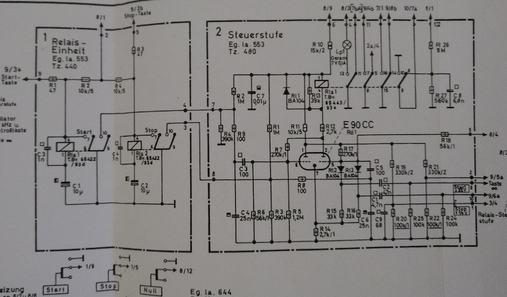
Unfortunately, the counter stopped working the next day - the tubes all displayed zeroes as would be expected but neither the counter nor the clock could be started by pressing the start button. The schematic on the right shows where I started the debugging process. Shown is the "Steuerstufe" which can be translated to "control stage". This is basically a flip-flop which is triggered by the start/stop switches shown on the lower left. Each of these two switches triggers one of the relays shown above which in turn will produce a pulse on the associated control lines at pin 3 and 7 respectively. Pressing these switches indeed triggered the relays but the flip flop did not switch. At first I looked for an impulse at the grids of the central E90CC. When I touched one of the leads of C3 with the oscilloscope probe, the capacitor just broke apart. Accordingly, I replaced C3 and C5 by two modern 100 pF capacitors, hoping that this would have solved the problem. |
|
|
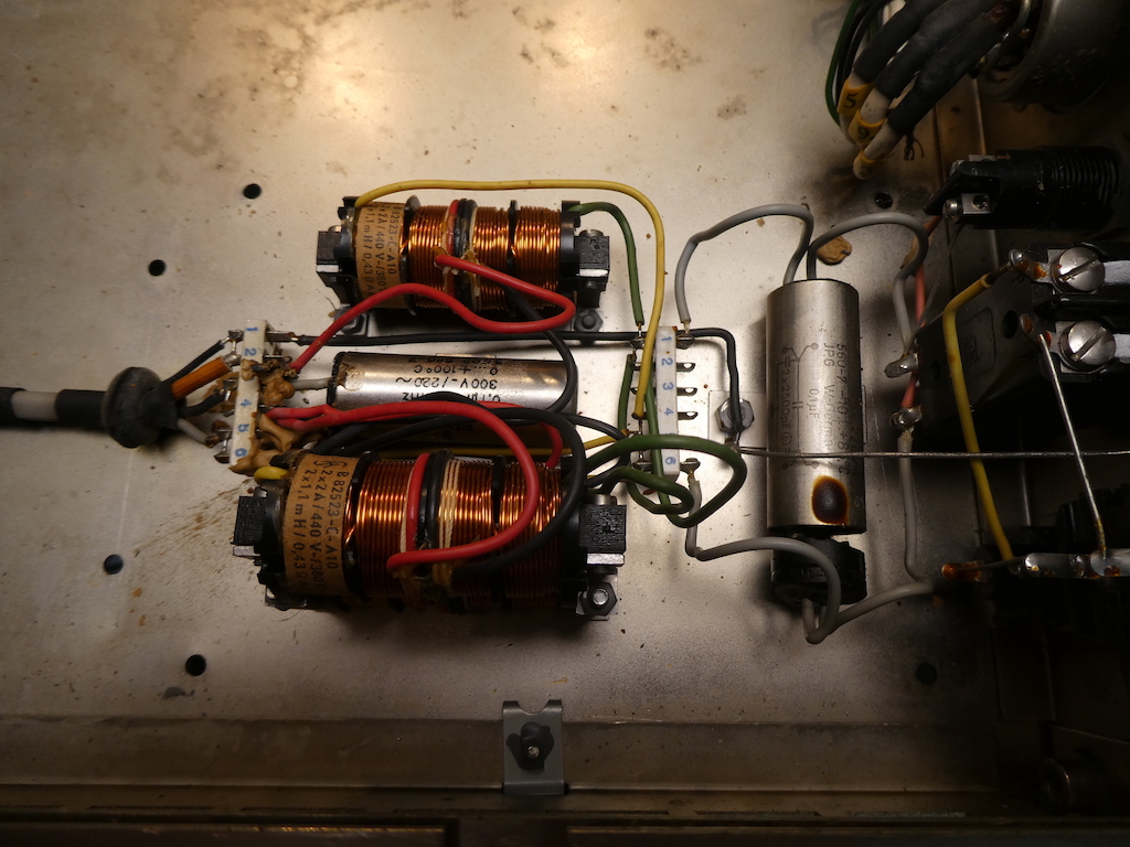
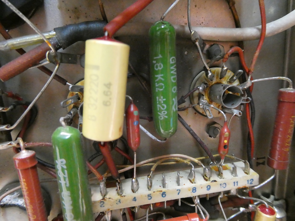
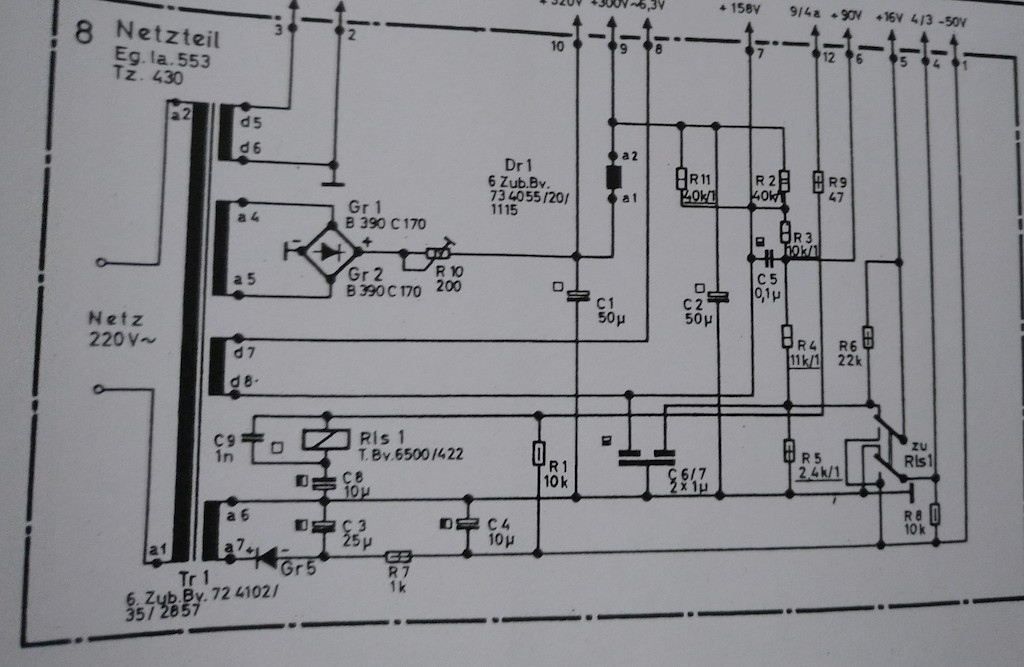
Unfortunately, the control flip flop still could not be triggered. After some head scratching I wondered about the purpose of the line at pin 5 in the schematic above. It is routed to 8/4 i.e. pin 4 of submodule 8 which is the power supply of this unit, the schematic of which is shown in the picture on the left. As can be seen, this line is tied to ground when then relay Rls 1 is not energized. A quick check showed this line at a potential of about -13 V which immediately explained the stuck flip flop. With the grid of the right half of the dual triode E90CC at such a negative potential it just could not be triggered. A little more investigation showed that Rls 1 is energized when the counter is reset. Since the reset line was not active, I checked the relay which sure enough showed a contact problem which could be resolved with fine cloth, a bit of patience, and a drop of isopropanol. After the relay contacts had been thoroughly cleaned, the counter came to life again. |
|
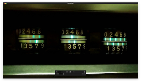
Clicking on the picture on the right will start a short video clip about four seconds in duration. Shown are the three rightmost digits of the counter being driven by a rather high frequency signal input. The Kompensograph mounted on top of the rack is still not working at all. Its rubber belts and pinch rollers have completely disintegrated over time. The ink bottle has cracked open and everything is covered in a thick film of dried red ink. Currently I wonder if I should replace it by another y/t-plotter or repair it which will take a lot of time and effort... Nevertheless, this wonderful machine is now operational again since the Kompensograph is not really necessary for its operation. |
|