|
|
| A True Random Number Generator |
|---|
| Before I got involved into computing, I was building small (sometimes even large :-) ) electronic devices, like specialized measurement equipment, analog/digital-converters and various other things. When I was working for the department of experimental and applied psychology at the Johannes Gutenberg University Mainz I got involved into biophysiological measurement techniques. Sometimes we had to build our own test and measurement equipment to perform some experiments involving test persons. For example they got presented very short sine tones via head phones and their EEG, EOG, EKG and EDA was measured. Some of these experiments required quite sophisticated equipment which got used more and more often. |
|
During this time I got into a discussion concerning telekinesis and telepathy - topics about which I am very (VERY! :-) ) sceptical about. In most cases I do not believe in things I did not measure myself, so I decided to develop a true random number generator, RNG-1 (this name was already in use for other random generators - a fact I did not know about then):
|
  |
|
|
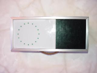
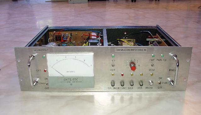
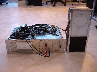
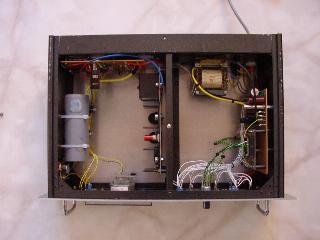
| These pictures show the entire system consisting of the random number
generator and a display unit. The random number generator itself is shown
in the middle and the display unit on the right. The random generator employs
a Geiger-Mueller tube to count the events generated by the decay of a Thorium
isotope. A microcontroller (a 68HC11) counts these pulses for a given delta-t
and sends the result to a serial line and the least significant bit (together
with a strobe signal) to a BNC-output. This output supplies a random zero
or one (TTL-level) at the moment of the strobe signal and is usually connected
to the display unit which consists of a circle built from LEDs showing a
moving light. Each time interval there is one LED switched on while the
remaining LEDs are in the off state. If - at the next strobe signal - there
is a zero on the random generator output the light "moves" to the right,
while it "moves" to the left in the event of a logical one. (The entire
display unit consists mainly of a 4 bit up/down-TTL-counter and 16 LEDs.) The random generator is somewhat more complicated. Its interior is shown on the next four pictures.
|
  |
|
|
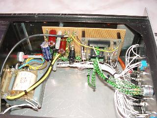
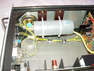
| The picture on the left shows the overall internal design. On the far
left is the Geiger-Mueller counter tube, next to it - on the rear - is the
high voltage controller and signal conditioner board, while the high voltage
power supply is located in the middle. On the right is the microcontroller
board. The second picture is a closeup of the counter tube assembly. The
tube is housed in a piece of plastic pipe which is mounted on the left side
of the crate. The third picture shows the high voltage control and signal
conditioning board - the microcontroller is shown on the last picture. The front panel of the random number generator contains the following elements:
|
|
|
|