|
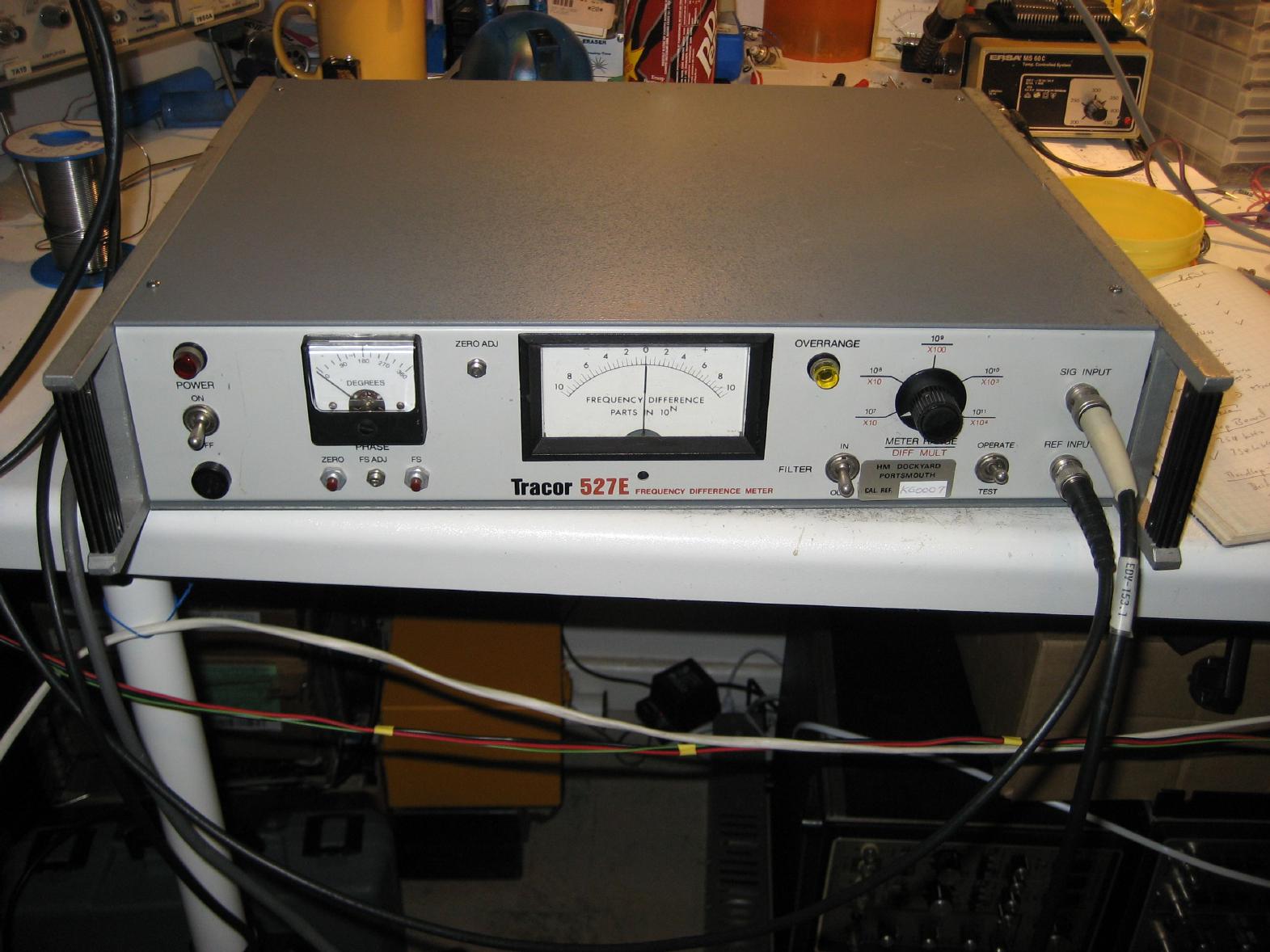
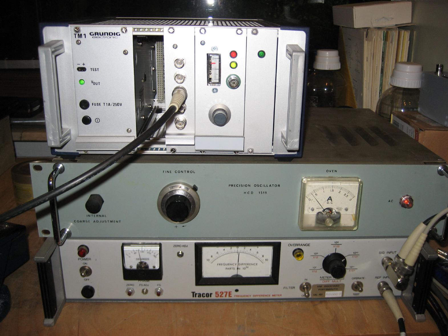
After my Rubidium osciallator was completed (more or less), I was looking for some way to compare other oscillators to this master oscillator in order to adjust them properly getting maximum performance out of them. As it is so often the case, I was incredibly lucky when I found TRACOR 527E Frequency Difference Meter at a liqudation of a small company that used to seel used instruments. The picture above shows this particular device which I acquired for 50 EUR. The picture shows the instrument after I performed a lot of cosmetic corrections and repaired the instrument - when I bought it, it looked rather shabby. It was missing the two small lamps (the red power indicator on the left and the yellow indicator for excessive frequency difference), there was no fuse holder, the power cord had been cut off and the enclosure was incredibly dirty. Cleaning the device took way more than an hour - it was plastered with stickers (one sticker read: "Defective!" - I was really afraid that I should have spent my 50 EUR for something else :-) ). The next step involved replacing the missing parts, the power cord etc. |
| Reparing the device: | |
|
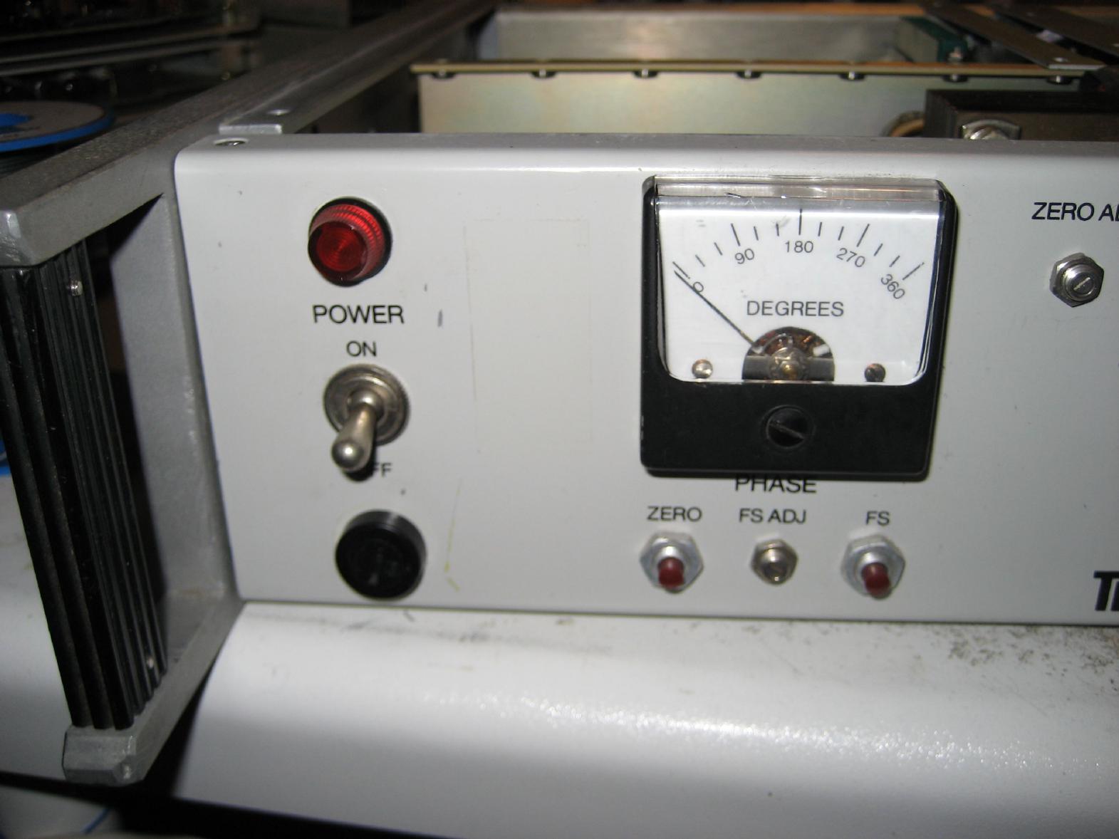
The first steps during the repair were pretty straight forward - I fitted in a new fuse holder, a new power cord etc. What turned out to be quite some challenge was to find some suitable indicators for power and excessive frequency difference. All I could find in my spare parts (garbage :-) ) bin were two nice lamp holders with neon bulbs! The problem was that the Tracor power these two missing indicators with low voltage while the neon bulbs were fixed into my lamp holders. It took quite a while to remove the neon bulbs and replace them with LEDs but the result was worth the time and effort spent. The picture on the right shows the new power indicator. |
|
|
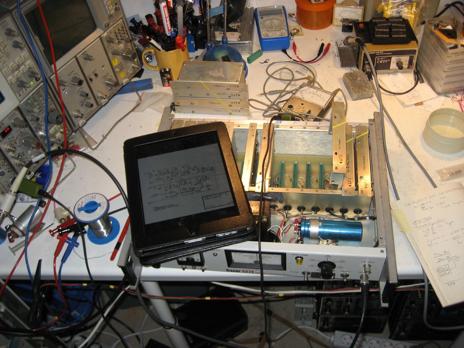
As the sticker reading "Defective!" already announced, the device turned out to be inoperable when I tried it for the first time with all of its boards in place (prior to this, I powered it on with only the regulator board in place to make sure that all voltages were within their respective limits with no excessive hum etc.). The picture on the left gives an impression of my debugging work - please note the iPad on top of the device. :-) My iPad is mostly used as a high comfort PDF-reader with Internet access and it has proven very useful during debugging sessions. Finally my table is no longer buried under paper manuals - instead everything I need in order to repair some device is on my iPad and ready for me to read, scroll or zoom into. Using modern technology to repair yesterday's devices is sheer pleasure! :-) |
|
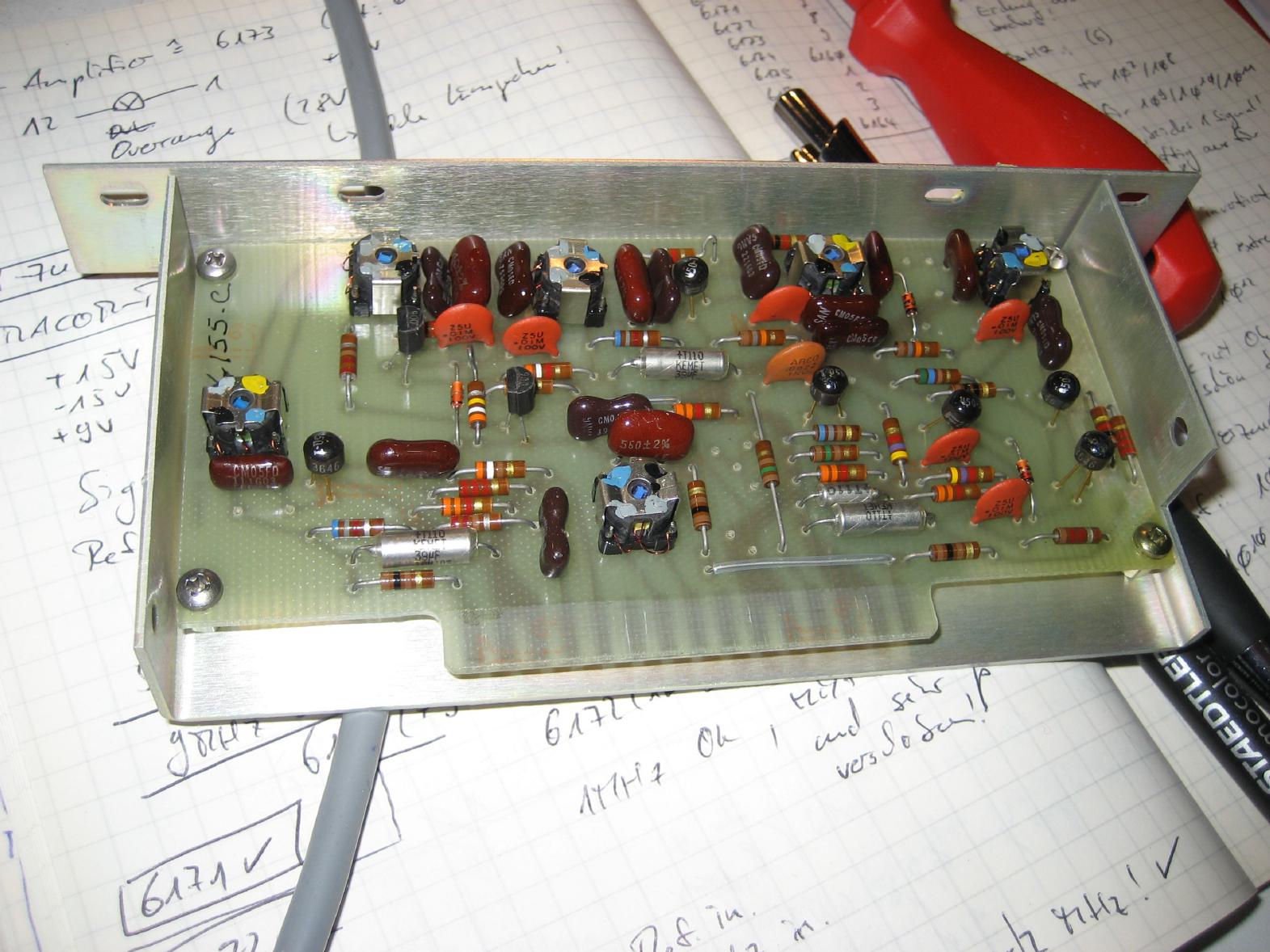
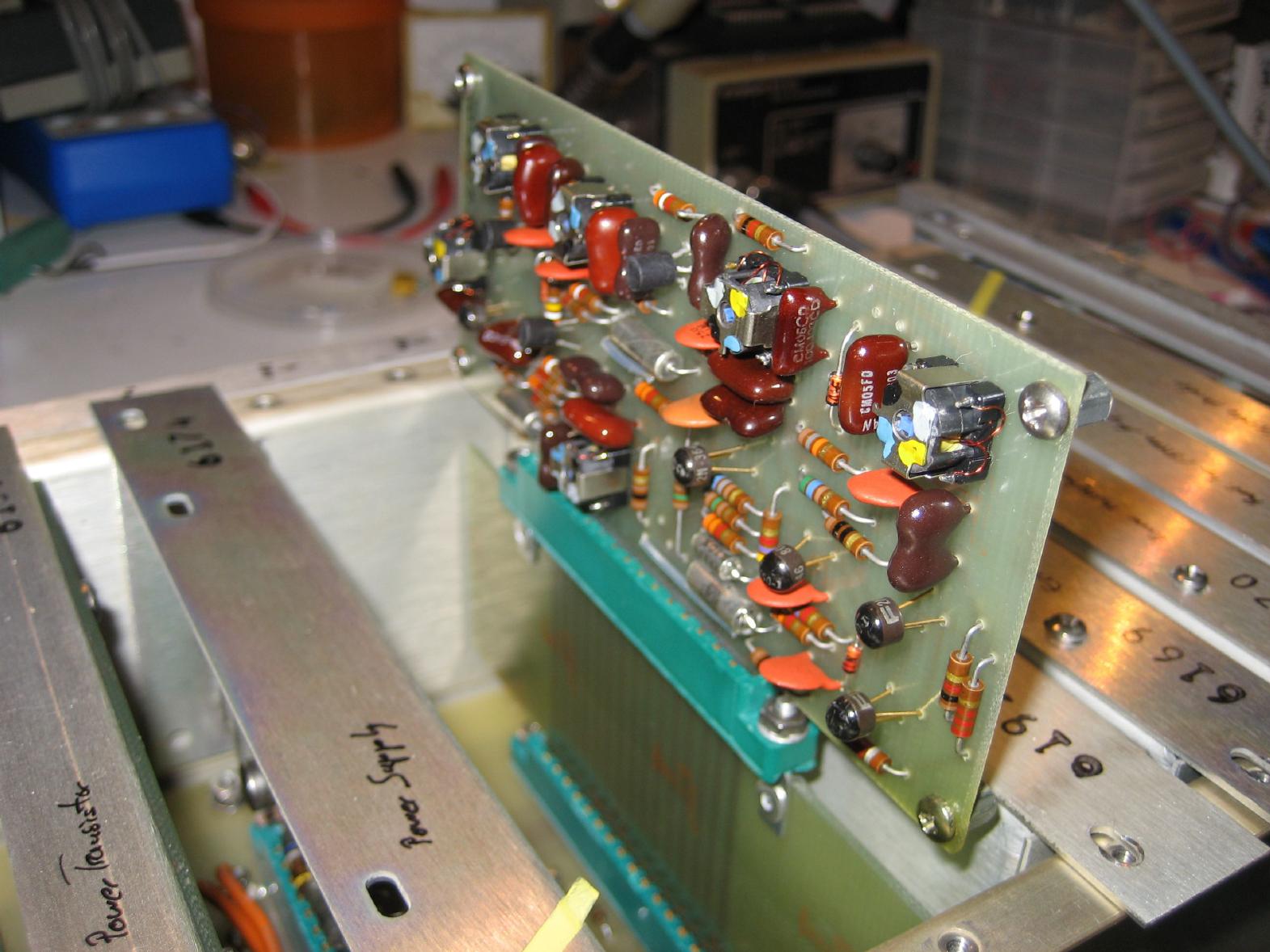
The Tracor 527E is based on a really clever idea - the so called error multiplier! This device multiplies the frequency error of an input signal as compared with a stable reference by a factor of ten. Therefore the signal in question which is a 1 MHz signal, is multiplied by 10 using a diode as non-linear device. The resulting 10 MHz signal is then mixed with a 9 MHz signal which is derived from the reference oscillator input yielding a 1 MHz signal which now has ten times the frequency difference of the original signal with respect to the reference input. The Tracor 527E uses four of these error multiplier boards in series. The picture on the right shows one of these error multiplier boards. One can see the mixer stage, the frequency multiplier etc. By the way - this is the board that was defective and rendered the overall device inoperable since it was the first error multiplier in the chain. |
|
|
The picture on the left shows the defective error multiplier on top of an extender board which was part of the Tracor 527E (I wish today's manufacturers would sell extender boards etc. with their devices - it would not be too expensive and it would make everybody happy who has to repair the device some day). As it turned out a single transistor in the mixer stage was defective. After replacing it, the error multiplier chain worked like a charm. The next problem that showed up was a very erratic display on the phase instrument. Unfortunately this was controlled by the only board I did not have the schematics for. :-) Fortunately it turned out to be caused be a bad solder joint and was fixed in a couple of minutes. |
| The device in operation: | |
|
The picture on the right shows the Tracor 527E in operation. On top of stack is the Rubidium oscillator which serves as my master oscillator. Below this is a HCD 1519 precision oscillator which I found on a scrap yard and bought for a couple of EUR. This is a quite bulky oven controlled quartz oscillator which I repaired a couple of weeks ago (broken power supply, missing oven current instrument). On the bottom is the Tracor 527E. As you can see, the HCD 1519 has already warmed up (oven current is well below 0.5 Ampere) and the frequency differency between it and the Rubidium oscillator is better than 0.5 parts in 10 ** 10. |
|
|
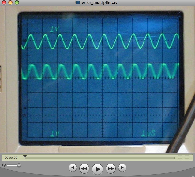
The short video clip on the left side shows the repaired error multiplier in operation. The top trace shows the 1 MHz reference signal while the bottom trace shows the output of the error multiplier with its frequency difference multiplied by ten. |
|
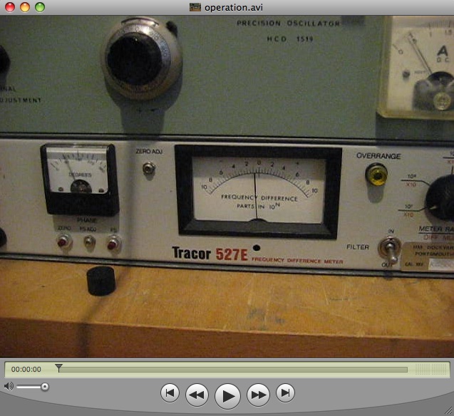
The short video clip on the right shows the instrument in operation. It compares the outputs of the Rubidium oscillator and the HCD 1519 precision quartz oscillator which is not yet up to temperature (as can be seen by the oven current which reads about 0.5 A). The frequency difference is already below 0.5 parts in 10 ** 7, but the phase meter on the left shows the phase difference between the reference signal and the output of the first error multiplier. |
|