|
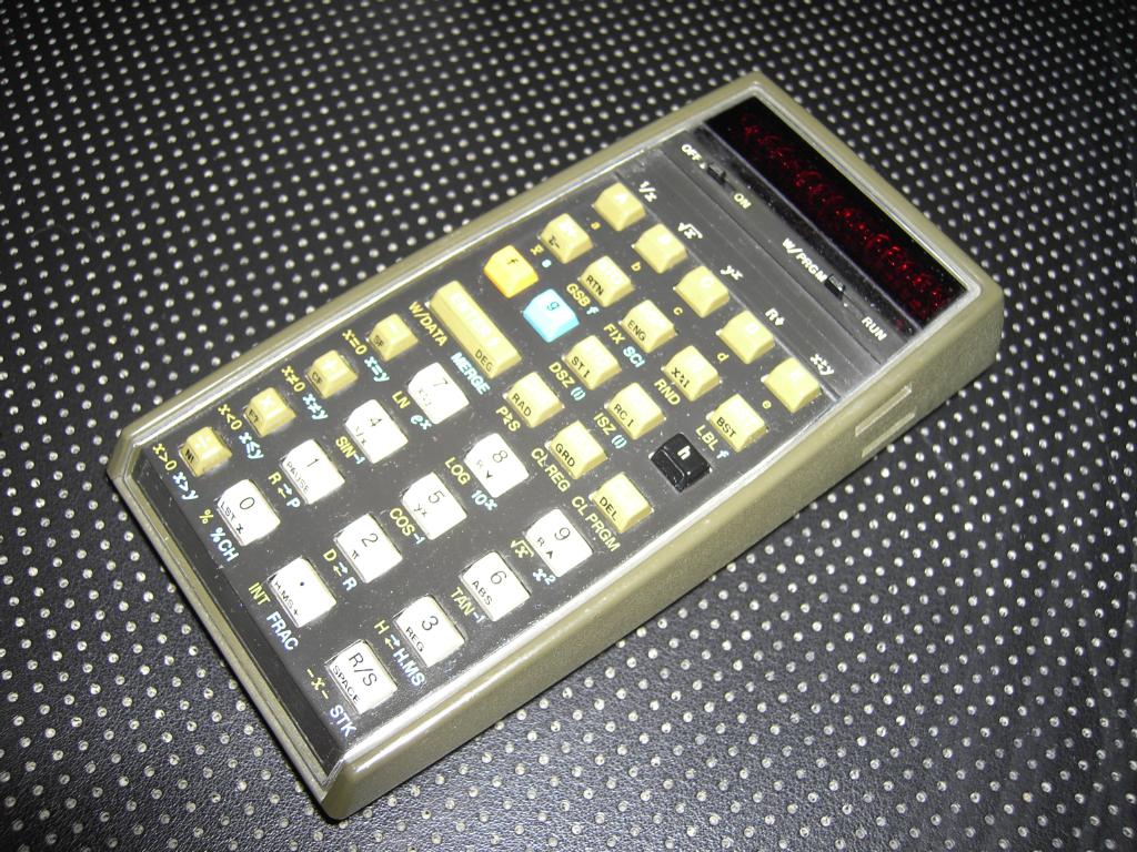
During this year's VCFE which took place in Munich as every year, I had the opportunity to buy a HP 67 programmable calculator (as well as an HP 41C) in unknown state at the VCFE flea market (and it can not be stated often enough, I have to give my wife a kiss here since she not only never complains about the fact that I spent far too much money for very obsolete calculators and computers but instead is as happy as I am about new old machines we get - thank you, Rikka, you are truly wonderful!). The HP 67 was HP's flagship programmable calculator in the late 1970s and the only competitor to Texas Instruments' TI-59. It features 224 merged program steps and 26 data registers (which is less than the TI-59 offers) and a built-in magnetic card reader/writer. As a true HP calculator it is a RPN machine in contrast to the TI-59 which uses an algebraic input method called AOS. The following sections describe my adventures in getting this calculator running again. What I bought was the bare calculator in unknown condition without batteries and without a power supply. |
| Repairing: | ||
|
Opening the HP 67 calculator is a bit tricky and it requires some patience to do it without harming the machine. All in all there are six screws holding the two parts of the enclosure together. Two screws are underneath the two rubber feet at the bottom of the machine, two screws are under the metal sticker showing the conversion factors (use extreme care and a very sharp knife to carefully remove this sticker without damaging it) while the last two screws are under the two rectangular plugs located on the top of the calculator. These can be removed with a sharp knife, too, and a bit of patience. |
||
|
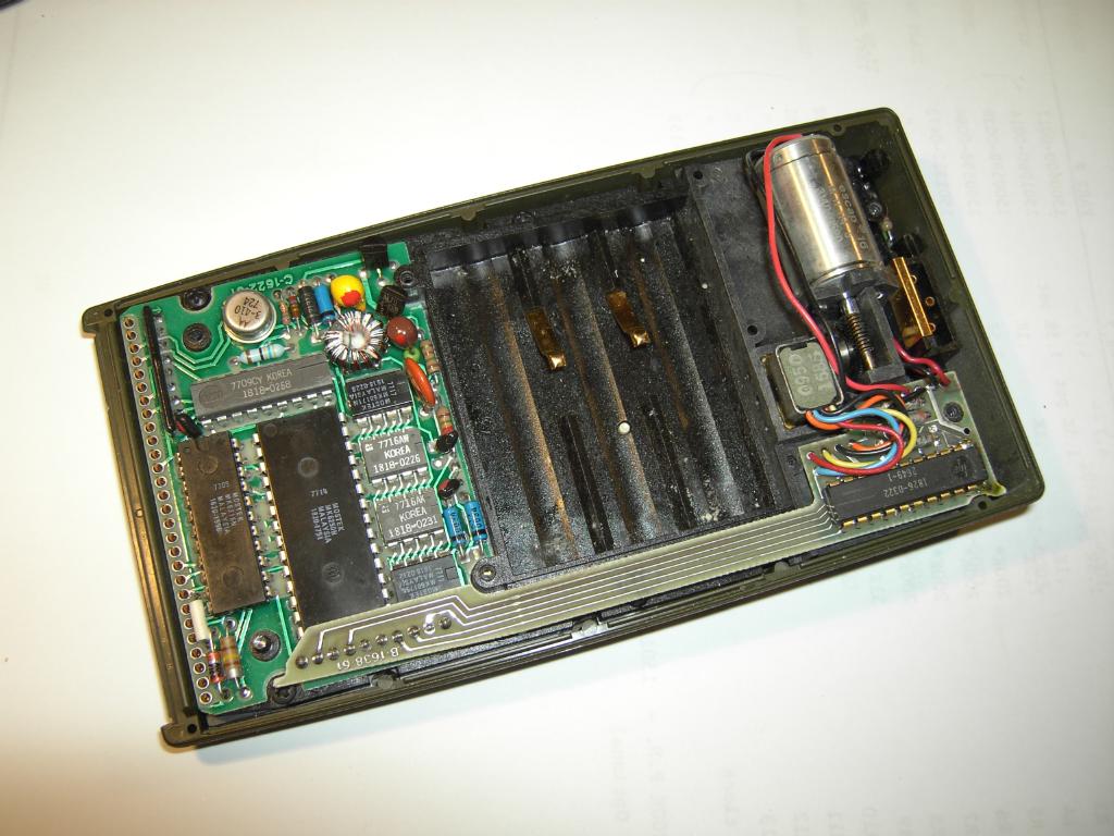
After removing the bottom plate of the enclosure you will see the interior of the calculator as shown in the picture on the right. On the left hand side the CPU board can be seen, in the middle the battery compartment can be found while the card reader/writer is located on the right hand side. |
|
|
|
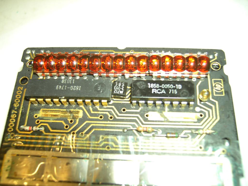
The picture on the left shows the display which is composed from three individual LED display strips containing five digits each. Below the display the display drivers can be seen as well as the two slider strips for the power and the run/program switch. |
|
|
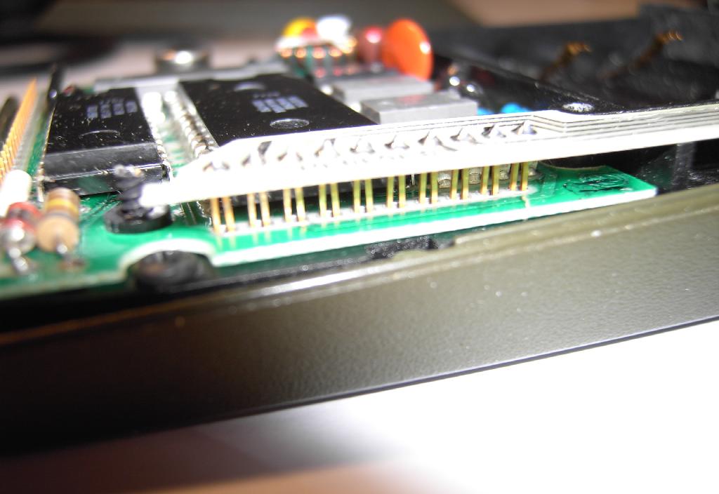
The connection between the card reader/writer and the CPU board is established by a long and quite fragile printed circuit board which holds the card reader interface on its right side (see above) and some connectors on its left side which plug directly into the CPU board. |
|
|
|
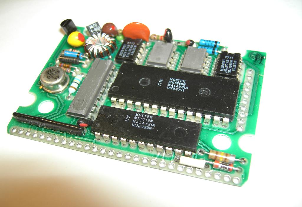
The CPU board is shown on the left - on the left side the connectors for the card reader/writer can be seen while the connectors on the bottom make the connection with the keyboard PCB of the calculator. |
|
|
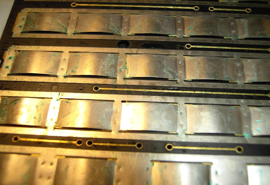
The keyboard and display circuitry and mechanics are mounted on a large common printed circuit board which can be seen in the picture on the right. The keys and the switches are separated by a rather thin sheet of plastic. |
|
|
|
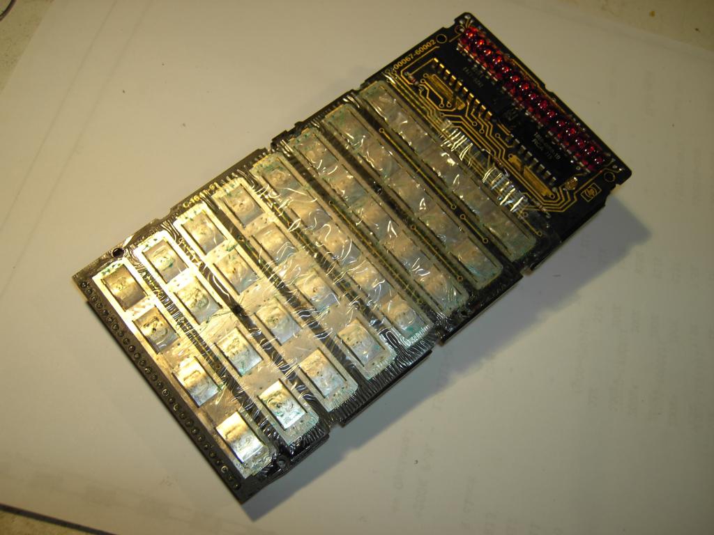
As can be seen in the picture on the left, the calculator once suffered from dying batteries - the keyboard shows signs of corrosion (clearly visible by the green deposits on the plastic sheet). I took the opportunity of having the calculator taken apart to thoroughly clean the keyboard and even apply some silicone oil to protect the switches from further corrosion. |
|
|
Nearly all calculators of this age show a defunct card reader/writer which is due to the rubber used in the card transport mechanism which turns into something rather ghastly over time. Therefore it is necessary to replace the transport wheel by something else. To accomplish this it is necessary to remove the deteriorated wheel from the card reader/writer. Shown in the picture on the right is the white plastic axle holding the wheel. This axle can be carefully removed using a screw driver to twist it and a pair of needle nose pliers to pull it out of the card reader/writer. |

|
|
|
To get to this point, the card reader has to be disassembled which seems to be quite easy - there are six screws holding its upper and lower half together (five screws are accessible from the bottom of the device, one is mounted from top). Please note: There are four small and precious plastic balls as well as a very fragile and important small plastic wheel on the bottom half of the reader/writer which tend to get lost while opening the device! I strongly suggest working on a very clean table - ideally inside a tub - to make sure that none of these parts gets lost! I personally secure the balls and the small (tiny!) wheel with a strip of duct tape and then remove them altogether with the tape storing them in a secure place until it is time to reinsert them. The four plastic balls will engage four control switches which are used to detect the presence of a card, its write-protect status, etc. while the tiny plastic wheel acts as the counterpart of the big rubber wheel pulling the card through the mechanism. In almost every case there will be some residue of the large, deteriorated rubber wheel on the small plastic wheel which has to be cleaned very carefully and very thoroughly. Even small amounts of debris will contaminate your precious magnetic card strips and will result in a lot of problems reading and writing cards! |
||
|
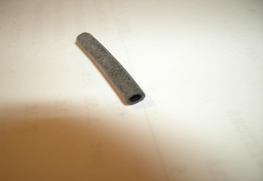
The deteriorated driving wheel is shown on the left - the rubber has completely decomposed - in fact I could peel it off just by rubbing with a finger on it. It takes some time to thoroughly remove any residue of this rubber from the wheel but it is necessary in the process of replacing the wheel by something else, so take some time for this procedure. |
|
|
How to replace the deteriorated rubber which has just been completely removed from the wheel? The standard procedure is to get some silicone tubing as it is used in model cars for the fuel lines with proper inner and outer diameters (about 6.3 mm). Unfortunately I could not find something suitable and had to think of something else. Fortunately a friend of mine gave me a large bag of rubber tubing as shown on the right. Normally this was used to insulate soldered wires in telephone exchanges and is of such high a quality that it still looks and feels like new despite its age of about 30 or 40 years. |
|
|
|
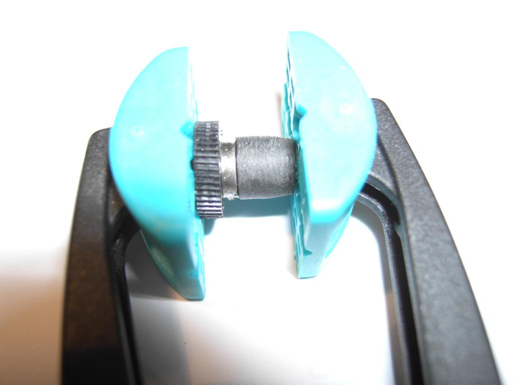
Of course these tubings have an outer diameter being too small to fit for this purpose but it is possible to put three of these tubings one over another which yields a nearly perfect outer diameter. To assure that this contraption does not fall apart in an instant, I glued them together using epoxy glue. The picture in the left shows the drying tubings mounted on the wheel but not cut to the final length. |
|
|
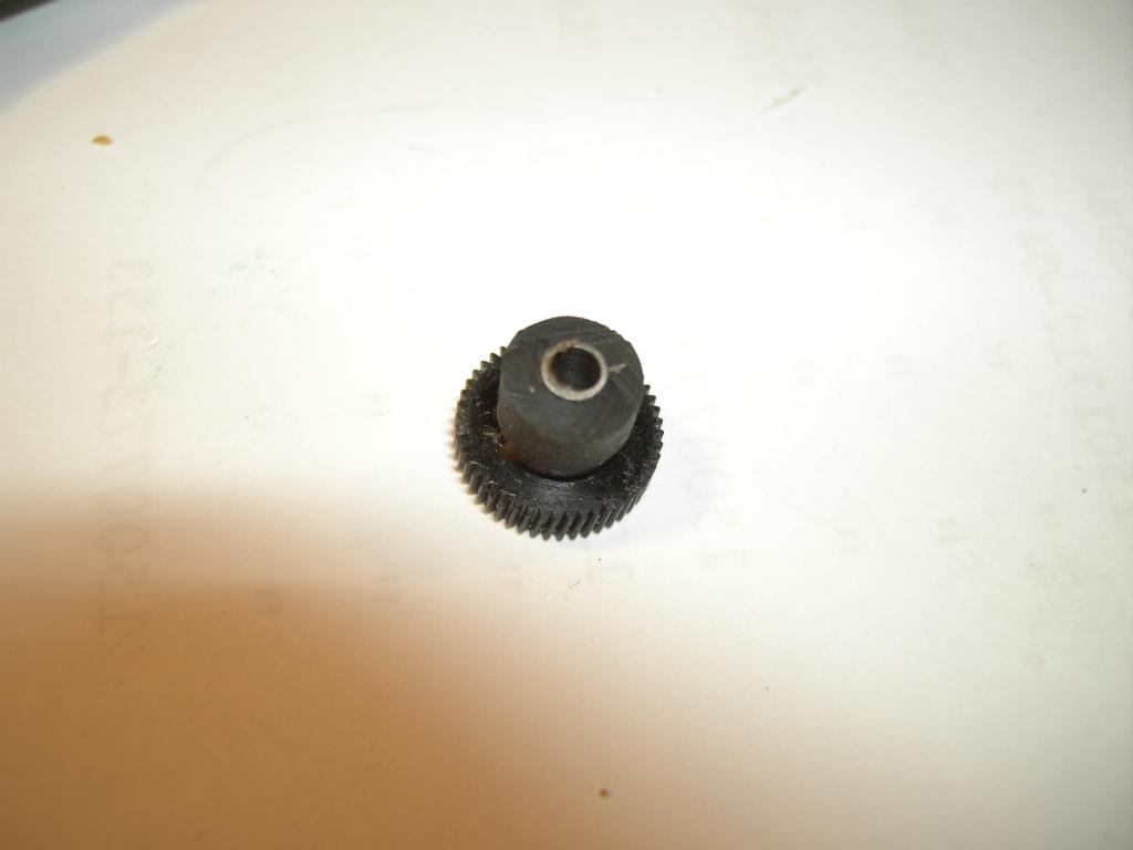
The picture on the right shows the final wheel with its three layers of rubber tubing after drying and after cutting the excess length away with a very sharp knife. The wheel works really great and very reliable although I used a different approach on a later restoration of another card reader/writer after I finally found some silicone tubing in a local model maker shop - it is just easier to have a single tube instead of fiddling with three at the same time. :-) |
|
|
|
After I completed the repair of the card reader/writer, I built a replacement battery pack using some off the shelf NiMH accumulators. Using a power supply I found in my collection of miscellaneous spare parts I could then switch on the calculator and it worked like a charm from the very first moment on. Thus I decided to take it with me when I went to the USA in May 2007 to attend the OpenVMS boot camp since leaving the house without a real :-) pocket calculator is no option at all and I thought I might need something to play with during the endless hours of boring flights. When I checked in they were puzzled by the HP 67 dangling from my belt and decided to check it thoroughly - the funny thing is that one man had a look at it and said: "What a beauty you have! In the 1980s I saw a lot of these but I haven't seen them for years!" - so even the security people at the airport know about HP pocket calculators. About in the middle of the week I would stay in the USA the card reader/writer operation became random and finally the reader/writer stopped working at all. Thus I had to take the HP 67 apart again after coming home to determine the source of the problem. |
||
|
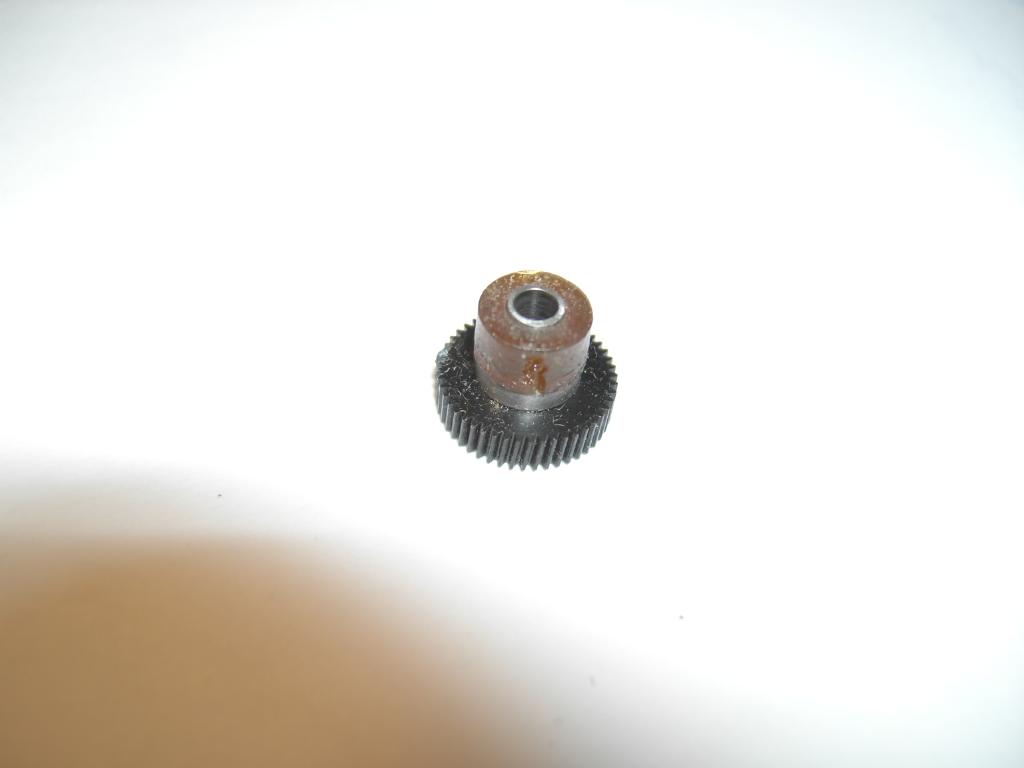
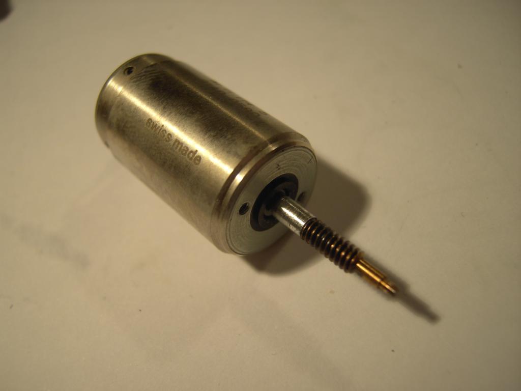
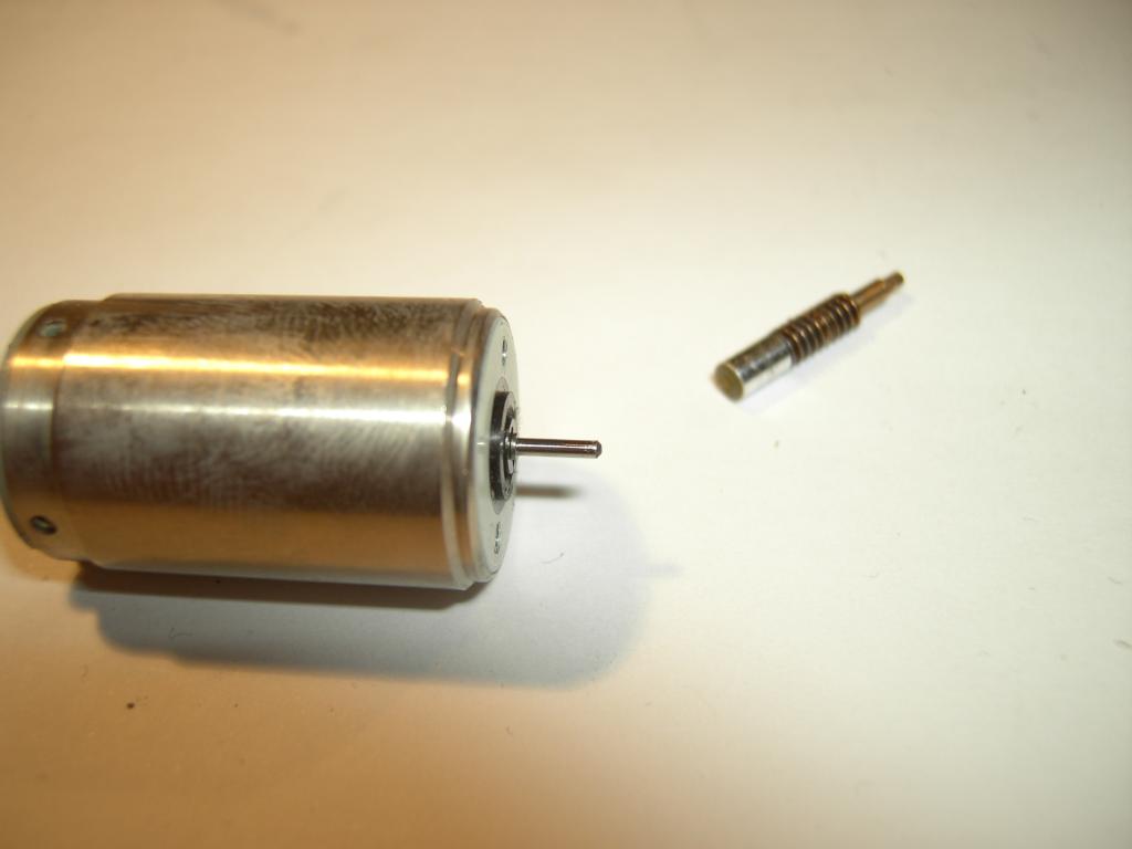
It turned out that the worm gear mounted on the shaft of the motor had turned loose resulting in insufficient torque to pull the card through the mechanism. The picture on the left shows the removed motor with its worm gear still mounted. |
|
|
Just gently pulling the worm gear separated it from the shaft of the motor, so I had to think about a way to get both parts fixed together reliably. As nearly always I decided to use epoxy glue - I mixed a very (very! :-) ) tiny amount of epoxy glue and put a fraction of a fraction of a ml into the borehole of the worm gear using a syringe. Then I pushed the worm gear onto the shaft of the motor and waited for the glue to harden. After reassembling the calculator again it now works flawlessly for quite some time while I am reading and writing quite a lot of cards, so the repair attempts were very successful. |
|
|
| Example programs | ||
|
Now having a working HP 67 in near mint condition (apart from some minor scratches on the keyboard) I had to write some programs for it. I have to admit it (and it is not that easy for me :-) ) that I like the HP way of programming a pocket calculator more than the Texas Instruments way (altough I normally preferred my trusty old TI-59 for my everyday calculations). While the method of programming the TI-59 quite closely resembles programming in machine language with every byte/word (name it as you like) occupying its own memory location without any connection to other memory cells, the HP programming methodology is more like assembly language programming as a simple example will make clear.
Assume that you want to perform an unconditional jump, a
HP's way of programming takes the instruction as a whole and saves
it into a single "line" of code (which still consists of several
bytes) which will be displayed at once and not piece by piece. The
same instruction In the following some rather short and ugly example programs are shown to give an impression of the way the HP 67 can be programmed. The following short (and rather unelegant) example program calculates the so called Ulam-series which is defined like this (for natural numbers):
The following program expects a number in the X-register of the stack and can be started by pressing A. It will then display the elements of the Ulam-series in succession and will terminate when the series reaches 1. The last number being displayed is the number of steps which was necessary to yield 1 for the given initial value.
|
||
|
The next program is a bit more sophisticated and not as unelegant as the prior one (although there is quite some room for improvements). It calculates the prime factors for a given value which is expected in the X-register on the stack. To run the program place the number to be factored in the X-register and press A. Whenever a factor is found the calculation will end, showing the factor. To resume calculation press R/S until 1 will be displayed denoting that there are no more factors.
All in all the HP 67 is a bit faster than the mighty TI-59 - although it lacks the large memory of the TI-59 and the ROM modules the TI-59 supports, the ease of programming makes the HP 67 more fun to play with (at least for me as I have to admit). A bit disturbing is the habit of HP calculators of not switching off the display during calculations resulting in what HP called "blurry display" - a bunch of flickering nonsense digits. The faint glowing "C" in the left most digit of a TI-59 is far more elegant and saves some power, too. The cards of the HP 67 (and its successors like the HP 41C) have only half of the data density of the TI-59 cards (two tracks compared with four tracks). Taking all this into account, it is a close race between the TI-59 and the HP 67 and if I had to decide which one to take on a lonely spot I would try to take both. :-) The HP 67 for the fun of programming it and the TI-59 for its large memory and its ROM modules. |
||
| Other resources on the net | ||
|
|
||